Ball retrieval system and method

a sports playing surface and ball retrieval technology, applied in the field of ball retrieval system and method, can solve the problems of slowing down the pace, reducing the useful operating time of the retriever, and not allowing players, so as to facilitate play, improve the useful operating time of the retriever, and improve the energy efficiency

Pending Publication Date: 2021-05-06
COURT BOTS INC
View PDF6 Cites 2 Cited by
  • Summary
  • Abstract
  • Description
  • Claims
  • Application Information

AI Technical Summary

Benefits of technology

[0014]In one embodiment, the passive detent is a concave portion on the sidewall of each blade to ensure retaining a collected ball until its planned release. A lower horizontally-extending ball guide cooperates with the opposing blade counterpart structure to guide the ball on release toward the target (and prevent the ball from reentering the detent area during the release). A ball proximity sensor signals the presence or absence of a ball in the collection space. Active detents be employed. A ball ejector can be added to expand the functionality of the retriever.
[0019]The invention in ground releases utilizes the forward motion of the retriever to release the ball toward a target. The target can be the center service line, or toward a player signaling via the player's remote control or similar device. The invention's ground release embodiments provide a fast and energy-efficient ball retrieval methodology.
[0021]The retrieval system can include an app on a smart phone or equivalent device to establish / initialize the standby position for the retriever, e.g. by the GPS functionality, preferably aside a net post. The retriever preferably includes an orientation sensor that coordinates with a programmed-in court grid for establishing retrieval paths and returns. The docking station may serve as a charging station for the retriever, for example by employing a coil induction-type charger, to extend the retriever useful operating time.
[0022]The invention provides an entirely new approach in automating and expediting play on tennis as well as other courts. Balls are collected and returned fast and efficiently utilizing the retriever's motion for ground releases in the programmed direction, e.g. toward the center baseline where a tennis player can easily collect the ball on the racket face. The invention's ground release embodiments are more energy efficient than alternative options, e.g. ball-lifting collection devices. Many players favor a baseline singles strategy, therefore returning retrieved balls there greatly facilitates play. Older players can opt to play singles with the assistance of the invention rather than having to resort to the doubles game. Overall, the energy expended in automatically retrieving a low-mass tennis ball is multiple orders of magnitude less than that of a player retrieving the ball. The invention also promotes maximum play-time (increasing the play to non-play ratio) to provide better value for the court rental cost, and to reduce match time. The latter consideration is particularly significant for tournament and other match play not utilizing ball-persons, for example in college or other scholastic matches. These matches sometimes employ a chair umpire, who can assist in expediting play by controlling retrievals as part of his or her tasks. The invention can decrease the number of, or even eliminate, ball-persons, e.g. by obviating the necessity for stationing one or more ball-persons at the net posts. Another benefit is ball-person safety, since ball-persons near the net are occasionally injured by ball strikes.

Problems solved by technology

Pickleball has a shorter net and does not allow players to come right up to the net—this is called the no volley zone.
An element common to all these play conditions, however, is that the amount of time spent in actual play (versus “non-play”, i.e. planned or forced pauses) is adversely impacted by players having to retrieve loose balls both while serving and after completing points, slowing the pace and thus affecting the quality and efficiency of play.
Professional tournaments address the issue by employing ball-persons for retrieving loose tennis balls in order to expedite play, a luxury not available for most due to the lack of fiscal or available manpower resources.
Court time is typically expensive, and of course time is money.
Players therefore often opt to play on despite the presence of loose balls on the court, which pose both a distraction and a safety hazard (a player may step on a ball and incur injury).
Although there have been solutions proposed or marketed to assist players in retrieving and picking up loose tennis balls, these are not designed for in-play.
Most of these tennis ball collection / retrieval systems are just manual collection devices requiring walking to each ball and therefore do not promote increased play time.
Wang notes that this adds to edge costs but also observes that a sparsity of obstacles allows for processing optimization and increased system response time and retrieval speed.
Like Eletrabi, the Wang robotic device is impractical for match play due to its large size, weight, processor overhead, and consequent power demand.
As with other prior art approaches, it employs a ball pickup mechanism, adding to its weight, complexity, and power overhead that altogether limit its collection capability.

Method used


Image

  • Ball retrieval system and method
  • Ball retrieval system and method
  • Ball retrieval system and method

Examples


example 1

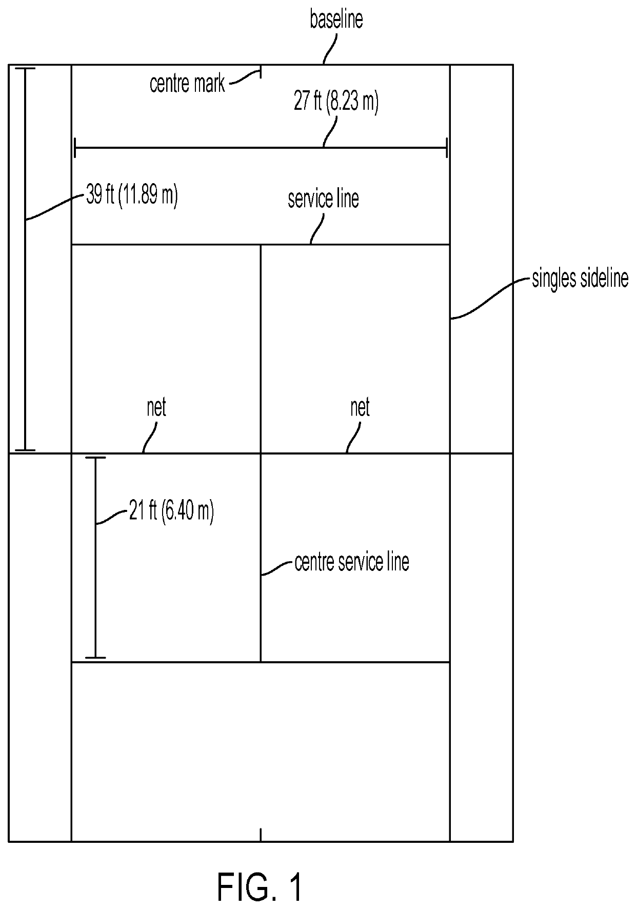
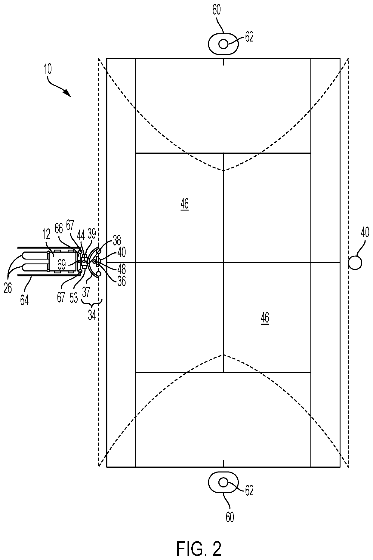
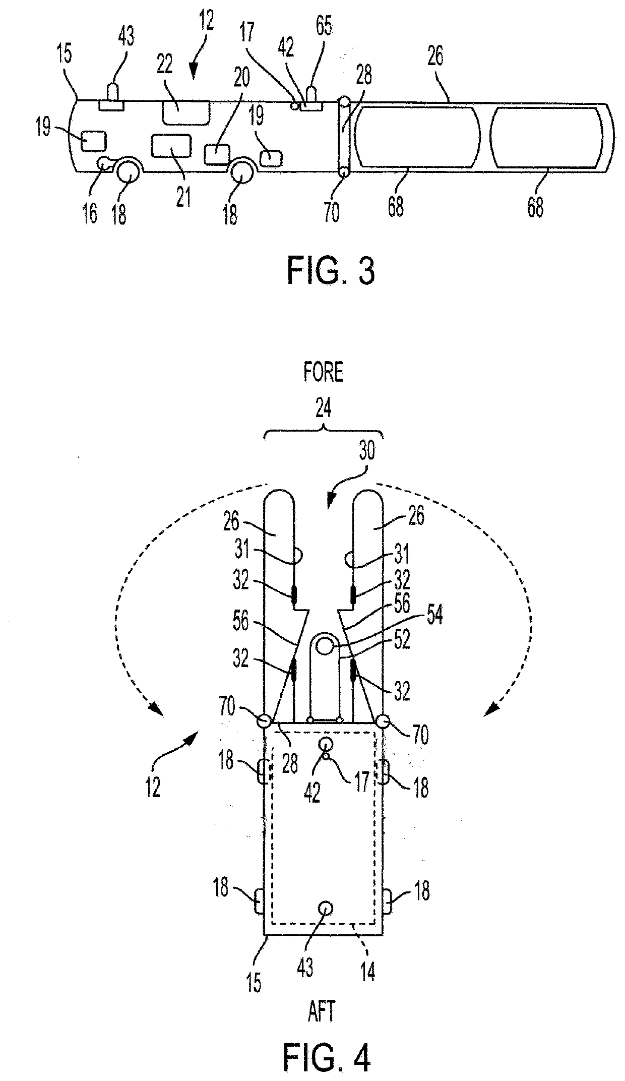
[0124]A retriever 12 was built by modifying an off-the-shelf Simrex A130 1 / 16 scale 2-wheel drive RC remote control off-road truck, with a ball collector 24 mounted thereon including opposing blades 26. The retriever was tested on a hard-court surface, successfully collecting balls at the net as well as in areas away from the net and releasing the balls toward the center service-mark on the baseline. A number of different blade configurations were thus tested in order to define and refine blade parameters such as length, contours, optimal sensor placements, and passive detent configuration and the like, to finalize the design parameters for the 3D-printed prototype blades (“test blades”).

[0125]The test blades 26 were fabricated as mirror-image structures of one another using an AutoCAD-programmed 3D-printing process employing acrylonitrile butadiene styrene (ABS) polymer, to the following specifications:

Description / DrawingDescription (“L” = length, “W” = width,Ref. Num.“D” = depth)...

example 2

[0127]The operating characteristics of the test blades were first studied by securing the blades in a) a stationary, fixed position and b) a rotatable position, and directing tennis balls at and into the test blades at varying angles and varying ball velocities, while video-recording the tests and studying the test blade performance frame-by-frame. Balls were fed through a 3″ ID 10′ length PVC pipe fitted within a 4″ ID 10′ length PVC pipe to provide both flexibility in varying ball velocity and to permit balls (≈2.7″ diameter) to freely exit the angled 4″ pipe opening. The pipes were set at differing heights at the feed end to produce varying ball exit velocities, from 3 ft / s to 10 ft / s.[0128](a) Stationary tests: tennis balls at higher velocities were captured effectively notwithstanding some bouncing off the fore spar. Lower velocity retrievals were routine.[0129](b) Rotating tests: the retriever was rotated upon a ball rolling past the fore sensor 32 slots at both higher and low...


PUM


Abstract

A remote-controlled retriever for collecting a ball on a sports playing surface and for controllably releasing the ball includes a front end ball collector having two spaced-apart blades defining a ball collection space. Each blade includes a passive or an active detent for retaining the collected ball in the collection space until a programmed or manually-directed release toward a target location such as a tennis baseline. The retriever includes a processor-controller for controlling and directing the retriever during a retrieval session.

Description

CROSS REFERENCE TO RELATED APPLICATIONS[0001]The present application claims the benefit of priority to U.S. Provisional Patent Application No. 62 / 756,450, filed on Nov. 6, 2018 and entitled “Tennis Ball Retriever System and Method”, and to U.S. Provisional Patent Application No. 62 / 908,267, filed on Sep. 30, 2019 and entitled “Tennis Ball Retrieval System and Method”.FIELD OF THE INVENTION[0002]The invention relates to a method and system for retrieving and returning a ball on a sports playing surface during play, and more particularly to a method and system for locating, retrieving, and returning a tennis ball to a programmed, manually-directed, or signaled target location on a tennis court.BACKGROUND OF THE INVENTION[0003]FIG. 1 shows the layout and the dimensions of a tennis court, where each baseline is the line intersected by its “center mark” and behind which a player is positioned when serving. The dimensions are as follows:Baseline: Doubles 36 feet (11 m) / Singles 27 feet (8....

Claims


Application Information

Patent Timeline
Patent Type & Authority Applications(United States)
IPC IPC(8): A63B47/02A63B69/40G05D1/00
CPCA63B47/021A63B69/40A63B2102/02G05D1/0011A63B2047/022G05D1/0094A63B24/0006A63B24/0075A63B71/0622A63B2024/0028A63B2024/0053A63B2071/025A63B2071/0611A63B2071/0625A63B2071/0627A63B2071/0655A63B2071/0677A63B2071/068A63B2071/0683A63B2102/08A63B2209/08A63B2220/10A63B2220/12A63B2220/34A63B2220/44A63B2220/80A63B2220/802A63B2220/803A63B2220/805A63B2220/806A63B2220/833A63B2225/02A63B2225/50A63B2225/74G05D1/0246G05D1/0278G05D2201/02A63B2220/05A63B2225/54
Inventor LEGG, LAWRENCE GEORGELEGG, SHANE F.
Owner COURT BOTS INC
Why Eureka
Try Eureka