
Electric apparatus of a vehicle having an at least partly electric braking and steering device

a technology of electric equipment and steering device, which is applied in the direction of braking system, braking components, vehicle sub-unit features, etc., can solve the problems of high component cost and system cost, low production efficiency, and relatively expensive installation cost,

Inactive Publication Date: 2021-05-06
KNORR-BREMSE SYST FUER NUTZFAHRZEUGE GMBH
View PDF0 Cites 3 Cited by
  • Summary
  • Abstract
  • Description
  • Claims
  • Application Information

AI Technical Summary

Benefits of technology

The invention allows for reliable braking even in the event of a fault in the power supply or brakes. It includes an additional electric service brake circuit that provides maximum braking power and reduces the risk of both circuits being put out of operation by the same fault. The invention also integrates a brake system with an electronic steering control device, reducing the need for expensive cabling. The closed-loop control of brake pressure helps to increase accuracy. Overall, the invention improves safety and reliability without adding significant cost.

Problems solved by technology

A disadvantage of this system configuration is the relatively costly installation and the high component costs and system costs.
As a result, such concepts are compatible with series production only to a limited degree.
Such a system is not suitable for (partially) autonomous or automated driving (autopilot) as described above, since, when such a fault occurs, automated controlled steering and braking interventions are no longer possible.
If a brake circuit were to occur, for example, during strong braking of an automatically controlled vehicle column (platooning) as described above, a rear-end collision would be unavoidable.

Method used


Image

  • Electric apparatus of a vehicle having an at least partly electric braking and steering device
  • Electric apparatus of a vehicle having an at least partly electric braking and steering device
  • Electric apparatus of a vehicle having an at least partly electric braking and steering device

Examples


first embodiment

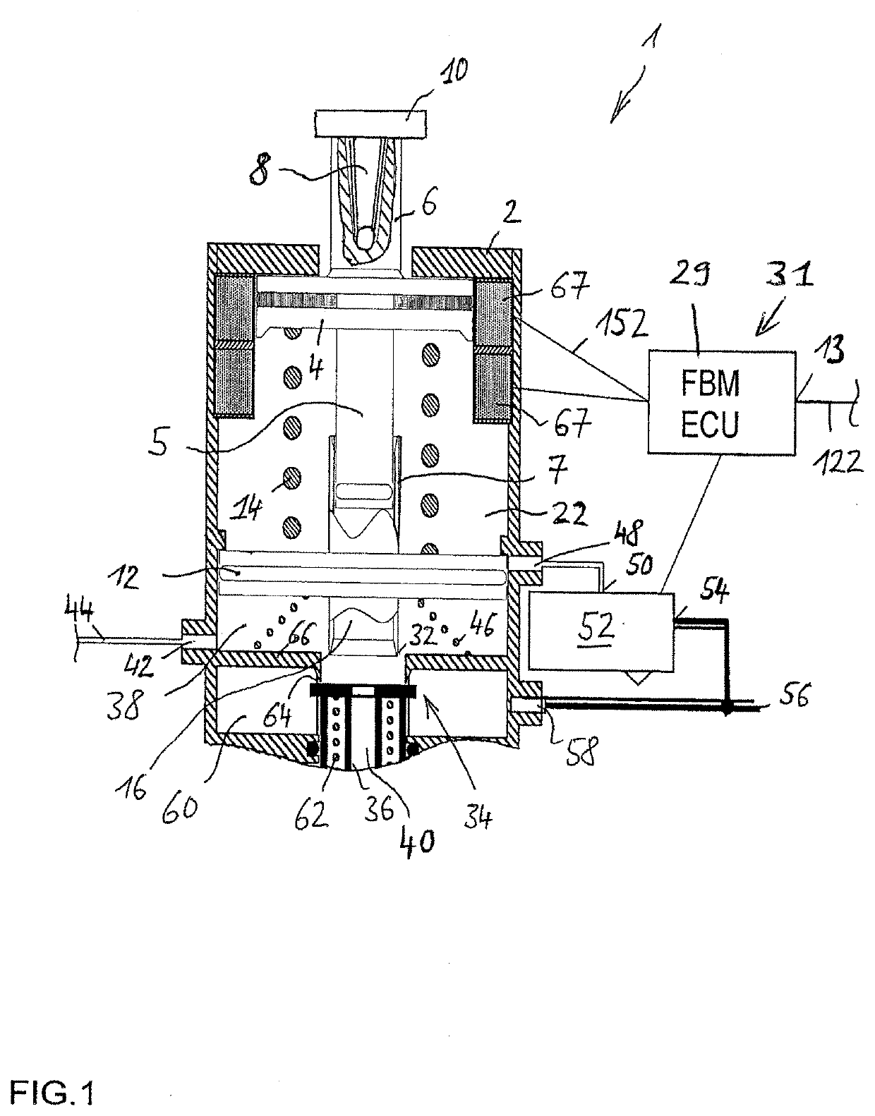
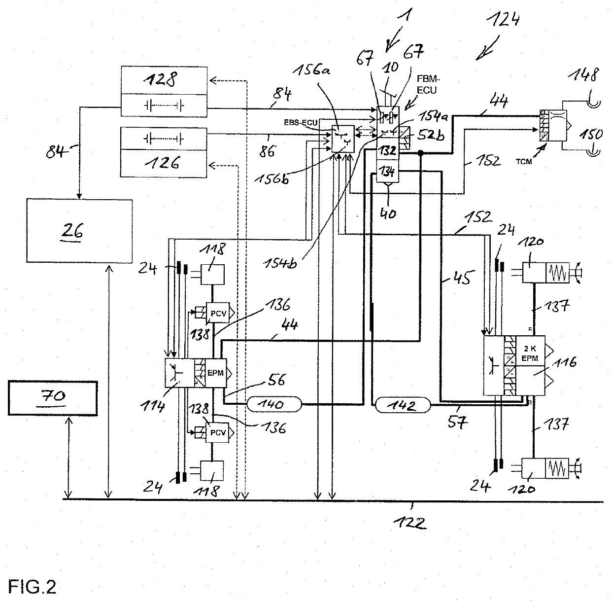
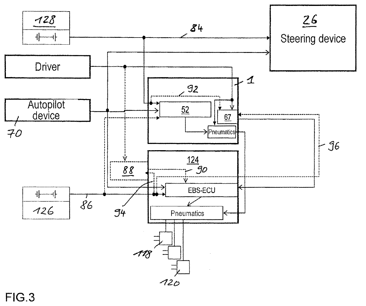
[0136] the steering device 26 or the electronic steering control unit 29 thereof and the service brake valve device 1 or the electronic control device FBM-ECU thereof are supplied with power by the second electric energy source 128, and the electropneumatic service brake device 124 or the brake control unit EBS-ECU thereof is supplied with power by the first electric energy source 126. The corresponding energy supply lines 84, 86 are characterized in FIG. 3 by unbroken lines with arrows in the form of triangular surfaces. The brake value generator 67 of the service brake valve device 1 is optionally also supplied with power here by the second electric energy source 128, as is indicated by the energy supply line 92 which is shown by dashed lines.

[0137]In this context, the electronic brake control device 1 of the electropneumatic service brake device 124 or the electronic control device FBM-ECU thereof is configured in such a way that it detects a failure or fault in a second electric...

second embodiment

[0138] there is provision that at least one electric signal generator 88, which is supplied with electrical energy, for example, by the first electric energy source 126 or by the first energy supply circuit via an energy supply line 94 (illustrated by a dashed line), and can be activated by the service brake activation element 10 is provided which, when the service brake activation element 10 is activated inputs an electrical activation signal into the electronic brake control device EBS-ECU via a signal line 90 which is shown by a dashed line in FIG. 3. In this context, the electric signal generator 88 can be integrated into the electropneumatic service brake valve device 1 and formed, in particular, by an electric switch.

[0139]According to a third embodiment, at least one electric signal generator 88 which is supplied with electrical energy by the first electric energy source 126 or by the first energy supply circuit and can be activated by the pneumatic brake pressure or brake co...

fourth embodiment

[0142] the electropneumatic service brake valve device 124 or the brake control unit EBS-ECU thereof is additionally supplied with electrical energy by the first energy supply circuit which contains the first electric energy source 126. In this context, the braking value generator 67 of the service brake valve device 1 is supplied with power by the second electric energy source 128 via the energy supply line 92.

[0143]In the third and fourth embodiments, the electric service brake circuit of the electropneumatic service brake device 124 receives the driver's braking request even in the event of failure of the first electric supply circuit or of the first electric energy source 126, and can implement said driver's braking request. As a result, the brake pressures in the wheel brake actuators 118, 120 can be correspondingly modified for steering braking, and can therefore implement both a driver's braking request and a steering request simultaneously. These embodiments are therefore al...


PUM


Abstract

An electric equipment component of a vehicle having an electric braking / steering device, including: a) an electric steering device with / without a continuous mechanical connection between a steering wheel and a steering gear mechanism, and an electronic steering control device and an electric steering actuator; an electropneumatic service brake device having an electropneumatic service brake valve device, an electronic brake control device, electropneumatic modulators and pneumatic wheel brake actuators; and a device having the electronic evaluation device of the electropneumatic service brake valve device and generating a second activation force independently of a driver's braking request, the further device acting on the control piston in the same or opposite direction to the first activation force when a braking request, independent of the driver's request, is present; the electronic evaluation device being integrated into the electronic steering control device, or the electronic steering control device being integrated into the electronic evaluation device.

Description

FIELD OF THE INVENTION[0001]The present invention relates to a piece of electric equipment of a vehicle having an at least partially electric braking and steering device and to a vehicle having a piece of electric equipment.BACKGROUND INFORMATION[0002]A combined and at least partially electric braking and steering device of a vehicle is discussed in the genus-forming document EP 0 999 117 A2. There is provision here that in the event of a fault in a steering system component, in particular a steering actuator, individual wheels for maintaining the steerability of the vehicle are selectively braked. As a result, the fault tolerance in the event of a failure of a steering system component is improved by virtue of the fact that an attempt is made to at least partially replace the failed steering effect of the respective steering system component by generating a yawing moment by selective braking of individual wheels. In order to increase the fail safety, the power supply of the combine...

Claims


Application Information

Patent Timeline
IPC IPC(8): B60W30/02B62D5/06B62D5/04B62D15/02B60T13/62B60T7/04B60T7/12B60T13/68B60T13/74B60T8/17B60T17/22B60W10/20B60W10/184B60T8/176B60T8/1755B60W60/00B60T8/88B60T13/58B60T15/02B60T8/171
CPCB60W30/02B60T2260/02B62D5/0481B62D15/025B60T13/62B60T7/042B60T7/12B60T13/683B60T13/74B60T8/17B60T17/221B60W10/20B60W10/184B60T8/176B60T8/1755B60W60/001B60W60/007B60T8/885B60T13/581B60T15/027B60T8/171B60T2220/04B60T2270/82B60T2270/406B60W2710/20B60W2710/18B60W2540/12B60T2270/306B60T2270/10B60T2260/09B60T2201/03B60T2270/402B60T2270/404B60T2270/413B60T2270/414B60T2270/88B60T2240/00B60T2250/03B60T2250/00B62D5/06B60W30/14B60W10/18B62D6/003B60W2520/28B60W2520/14B60W2520/105B60Y2400/306B60Y2400/3032B60Y2400/304
Inventor HECKER, FALKSTEINBERGER, JUERGEN
Owner KNORR-BREMSE SYST FUER NUTZFAHRZEUGE GMBH
Learn More