Imaging assays

a technology of assays and images, applied in the field of assays, can solve the problems of inability to detect biomarkers, same problems of detection and diagnosis, and techniques suffer from drawbacks, so as to increase the mass of marker species and increase the scattering of light

Pending Publication Date: 2021-05-06
OXFORD NANOIMAGING LTD
View PDF4 Cites 2 Cited by
  • Summary
  • Abstract
  • Description
  • Claims
  • Application Information

AI Technical Summary

Benefits of technology

[0036]In all embodiments of the invention, the steps of contacting and incubating the sample with the first proximity probe and contacting and incubating the sample with the second proximity probe may be performed sequentially (step (i) followed by step (ii) or step (ii) followed by step (i)) or simultaneously. Preferably, however, they are performed sequentially and particularly preferably with step (i) followed by step (ii). Optionally, steps (i) and (ii) are performed sequentially and a washing step is performed in between steps (i) and (ii). Any suitable washing buffer may be employed for the washing step. The washing step helps to remove molecules from the sample which have not been bound by the first proximity probe or non-specifically bound to the support, thereby helping to minimise any background fluorescence or light scatter.
[0164]Each of the plurality of first proximity probes is tethered to a solid support by a polymeric or biopolymeric tether molecule. In one embodiment each of the plurality of first proximity probes is tethered to the support by a separate tether molecule such that each tether molecule carries one type of first proximity probe. Preferably, however, each of the plurality of first proximity probes is conjugated to the same tether molecule. Each of the plurality of first proximity probes in such embodiments is tethered to a different site on the same tether molecule. dsDNA and DNA origami structures are particularly suitable tether molecules for such purposes. DNA origami structures may have a plurality of binding sites for proximity probes and thus a plurality of first proximity probes (for example two, three, four or more first proximity probes) having specificity for different antigens may be conjugated to the origami structure. Optionally, multiple DNA origami structures may be employed simultaneously in this fashion in order to allow further discrimination between different origamis and / or different capture probe sites and thus further increase the number of analytes which can be detected in parallel. Where multiple DNA origami structures are employed, the first proximity probes may first be conjugated to the origami structures before the origami structures are tethered to the solid support.

Problems solved by technology

At very early stages of a disease the level of biomarkers present in body fluid samples may be below the level of detection (LOD) of current assay techniques and therefore such biomarkers may not be detected, or may be detected only at low levels which do not permit a confident diagnosis to be made.
Low levels of biomarkers may also be present in the case of some non-early-stage diseases, giving rise to the same problems of detection and diagnosis.
However, such techniques nevertheless suffer from drawbacks which it is desirable to overcome.
For example, the “Simoa” techniques have a limited dynamic range and do not give quantitative results at analyte concentrations above about 10−14 M.
Variation in the stoichiometry of antibody-antigen binding, antibodies sticking to the reaction chambers, and inherent stochasticity of diffusing molecules introduce significant margins of uncertainty to the quantification of antigens detected using such techniques.
Both Simoa and SMC / Erenna techniques employ costly and large (˜1.5-3 m3) instruments which require significant lab space.
Further, despite the fact that ELISA protocols conventionally employ a blocking buffer which is intended to prevent non-specific binding of reporter antibodies to the solid support, a certain degree of non-specific binding will inevitably take place even in highly-sensitive assays such as Simoa, SMC or Erenna assays.
These background signals constrain the LOD and limit the ability of conventional ELISA-based techniques to provide accurate quantification of analyte concentrations.
Where the sample to be analysed is a body fluid sample (e.g. a blood or cerebrospinal fluid sample) this can require the extraction of large volumes from a patient, which can be an unpleasant experience.

Method used


Image

  • Imaging assays
  • Imaging assays
  • Imaging assays

Examples


example 1

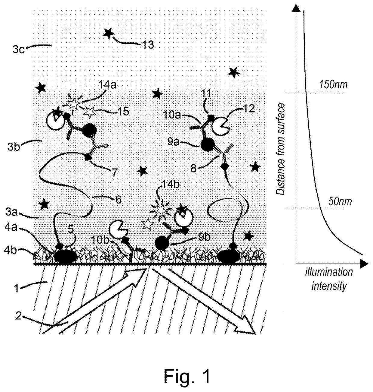
[0172]FIG. 1 shows an illustrative embodiment of a method according to the invention. In this embodiment, an assay is performed on the surface of a glass support (1). A total internal reflection (TIR) illumination scheme (2) is employed. TIR generates an evanescent illumination field that decays exponentially within a few hundred nanometres of the interface (illustrated on the right of the Figure). The medium can be conceptually divided into regions of high (3a), intermediate (3b) and low (3c) illumination density. The surface of (1) is silanized and passivated using biotinylated BSA (4a) and Tween-20 (4b). Interaction (5), which can, for instance, be a covalent bond or a biotin-streptavidin-biotin interaction, leads to the binding of a 1 kb dsDNA tether (6) to the surface (1) via BSA (4a). Interaction (7), which can, for instance, be a biotin-streptavidin-biotin interaction, binds capture antibodies (8) onto the dsDNA tether.

[0173]A serum sample was loaded onto the functionalized s...

example 2

[0176]This example illustrates a simple protocol for the passivation of a microscope slide or coverslip. This protocol may also be employed for treating microfluidic chips.

[0177]The coverslip is placed in a staining jar and rinsed with ultrapure water. The staining jar is then filled with fresh high-purity acetone in order to remove any organic compounds which might otherwise interfere with fluorescence measurements. The staining jar containing the coverslip and acetone is placed in a sonicator and sonicated for about 20 minutes. Following sonication, the acetone is discarded and the coverslip rinsed again with ultrapure water. After rinsing, the staining jar is filled with 1M KOH and sonicated again for about 20 minutes. The KOH is discarded and the coverslip is rinsed again with ultrapure water. A further sonication step of about 20 minutes is performed with the coverslip immersed in ultrapure water and then the coverslip is dried using nitrogen gas. Optionally, the coverslip may ...

example 3

[0182]This Example illustrates one possible implementation of the method of the invention.

[0183]dsDNA is employed as a tether molecule in this Example, although this protocol can be adapted for use with any suitable tether. A passivated microfluidic chamber is employed as the solid support, although this protocol can also be adapted for any form of solid support contemplated herein. The microfluidic chamber may be passivated according to the protocol described in Example 2, for instance.

[0184]The concentration of dsDNA solution is optimised to allow about 300 to 400 tether molecules to be immobilised on the solid support. The tether molecule solution is introduced into the microfluidic chamber and incubated for about 2 minutes. Unbound tether molecules are removed by washing with an appropriate buffer and then 50 μl of a 10 nM solution of the first proximity probe are introduced into the microfluidic chamber. This solution is incubated for about 5 minutes and then any unbound probe ...


PUM

PropertyMeasurementUnit
mean end-to-end distanceaaaaaaaaaa
volumeaaaaaaaaaa
volumeaaaaaaaaaa

Abstract

The present application relates to assays and systems for the detection of analyte molecules in a liquid sample, preferably a biological sample. In particular the invention relates to a method for determining the presence of a target analyte in a liquid sample, comprising contacting and incubating the sample with a first proximity probe comprising an analyte-binding domain having specificity for the target analyte, wherein the first proximity probe is tethered to a solid support by a polymeric or biopolymeric tether molecule which alters the observed properties.

Description

[0001]The present application relates to assays and systems for the detection of analyte molecules in a liquid sample, preferably a biological sample.[0002]Antibody-based analytical techniques are popular and well-known analytical techniques which have been widely adopted in biochemistry and medicine for the qualitative and quantitative detection of analytes in liquid samples. The most common type of antibody-based assay is the enzyme-linked immunosorbent assay, or “ELISA”. A variety of different ELISA techniques are known, all of which fundamentally rely upon the specific binding of an enzyme-labelled antibody to an antigen.[0003]Due to the high specificity of antibody-antigen interactions, ELISA techniques are renowned for their high sensitivity and ability to detect antigens at low concentrations. This sensitivity has led to the widespread adoption of ELISA in applications such as detection of the presence of antibodies in serum samples to determine the presence or absence of a d...

Claims


Application Information

Patent Timeline
Patent Type & Authority Applications(United States)
IPC IPC(8): G01N33/543G01N33/542
CPCG01N33/54353G01N33/54393G01N33/542G01N33/543G01N33/54373
Inventor CHANDRADOSS, STANLEY DINESHJING, BOLI, MENGQIU
Owner OXFORD NANOIMAGING LTD
Why Eureka
Try Eureka