
Circuit arrangement, method for operating a circuit arrangement and electrolysis device

a circuit arrangement and circuit technology, applied in the direction of electric variable regulation, process and machine control, instruments, etc., can solve the problems of complex implementation, risk of operation of one or more electrolysers outside of their safe operating range, and substantial derating

Pending Publication Date: 2021-05-13
SIEMENS ENERGY GLOBAL GMBH & CO KG
View PDF7 Cites 1 Cited by
  • Summary
  • Abstract
  • Description
  • Claims
  • Application Information

AI Technical Summary

Benefits of technology

The invention is a circuit arrangement for safely and efficiently operating multiple electrolycers in a safe operating range. The arrangement includes a rectifier and down-converters for each electrolyzer, which allows for individual control and adjustment of each electrolyzer. This avoids problems such as current distribution and derating of the electrolyzers. The use of a single transformer reduces iron losses and simplifies the design of the circuit. The arrangement also includes multiple switches and a capacitor for buffering energy and stabilizing the first DC voltage. Overall, the invention improves energy efficiency and ensures safe and reliable operation of the electrolycers.

Problems solved by technology

It has been known hitherto that multiple electrolysers are connected in series for this purpose, each of the electrolysers being supplied with power via a separate DC isolated circuit comprising a transformer having a tap changer for coarse control of the electrolysers and a rectifier having a thyristor circuit for fine control of the electrolysers, which is a very complex implementation.
As an alternative, to reduce the circuitry, it is also known for the electrolysers to be connected in parallel and also operated via a rectifier, but this can result in a current distribution according to the resistance ratios of the electrolysers and hence in substantial derating and also the risk of operation of one or more electrolysers outside of their safe operating ranges.

Method used


Image

  • Circuit arrangement, method for operating a circuit arrangement and electrolysis device
  • Circuit arrangement, method for operating a circuit arrangement and electrolysis device

Examples


Embodiment Construction

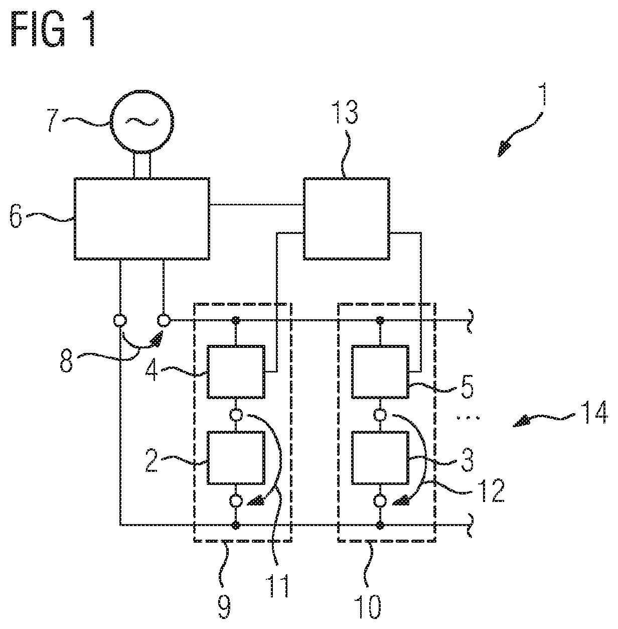
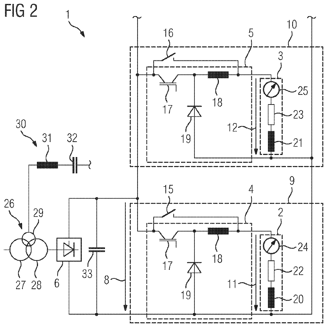
[0026]FIG. 1 portrays a schematic depiction of a circuit arrangement 1 according to the invention. The circuit arrangement 1 is used for supplying DC current to multiple electrolysers 2, 3 connected in parallel, wherein each of the electrolysers 2, 3 is connected in parallel with the output of a rectifier 6 via a down-converter 4, 5. The rectifier 6 converts an AC voltage 7 present on the input side into a first DC voltage 8. This first DC voltage 8 is dropped across the branches 9, 10 comprising in each case one of the electrolysers 2, 3 and one of the down-converters 4, 5.

[0027]The first DC voltage 8 is converted by the down-converter 4 into the second DC voltage 11, which is dropped across the electrolyser 2. Accordingly, the first DC voltage 8 is likewise converted by the second down-converter 5 into the second DC voltage 12, which is dropped across the electrolyser 3. In addition to the two depicted electrolysers 2, 3, the circuit arrangement can naturally also be used for supp...


PUM


Abstract

A circuit arrangement and to a method for operating the circuit arrangement, particularly a circuit arrangement for the DC power supply of a plurality of parallel electrolysers, where the circuit arrangement has a rectifier which converts an input-side alternating voltage into an output-side first DC voltage. Each electrolyser is respectively connected in parallel to the output of the rectifier by a down converter converting the first DC voltage into a second DC voltage such that the second DC voltage drops over the electrolyser. Each of the down converters is controllable and / or regulatable in order to adapt the level of the second direct voltage.

Description

CROSS REFERENCE TO RELATED APPLICATIONS[0001]This application is the US National Stage of International Application No. PCT / EP2019 / 059616 filed 15 Apr. 2019, and claims the benefit thereof. The International Application claims the benefit of European Application No. EP18168178 filed 19 Apr. 2018. All of the applications are incorporated by reference herein in their entirety.FIELD OF INVENTION[0002]The invention relates to a circuit arrangement for supplying DC current to multiple electrolysers connected in parallel. Furthermore, the invention relates to a method for operating such a circuit arrangement and to an electrolysis device.BACKGROUND OF INVENTION[0003]Electrolysis, that is to say processes in which a chemical reaction is brought about using electric current, is employed in many technical fields and is used for example to produce various substances. For example the electrolysis of water can produce hydrogen and oxygen. To operate electrolysis apparatuses, also called electro...

Claims


Application Information

Patent Timeline
IPC IPC(8): C25B9/65C25B1/04C25B13/00C25B9/23C25B15/02H02M3/155
CPCC25B9/65C25B1/04H02M3/155C25B9/23C25B15/02C25B13/00C25B9/73Y02E60/36H02M1/007H02M3/156H02M7/162H02J7/02
Inventor UTZ, PETER
Owner SIEMENS ENERGY GLOBAL GMBH & CO KG
Learn More