Unlock instant, AI-driven research and patent intelligence for your innovation.

Micro LED display device

a display device and micro-lead technology, applied in the field of display devices, can solve the problems of increasing the manufacturing cost, reducing the life of the oled device, and low power efficiency and brightness of such kind of lcd devices b>100/b>, and achieve the effect of increasing the light conversion efficiency

Inactive Publication Date: 2021-06-03
YINGLIGHT TECH
View PDF0 Cites 0 Cited by
  • Summary
  • Abstract
  • Description
  • Claims
  • Application Information

AI Technical Summary

Benefits of technology

The patent text states that the use of quantum dots can improve the efficiency of converting light emitted by micro LEDs. This increase in conversion efficiency can lead to improved performance of the micro LED display. Specifically, quantum dots can enhance the amount of light that passes through the color filter, resulting in better color representation and reduced power consumption.

Problems solved by technology

However, the power efficiency and the brightness (contrast) of such kind of LCD device 100 is low because only few lights emitted from the backlight module 111 can pass through the liquid crystal layer 116.
Furthermore, the manufacturing processes of the transistor layer 114 are complicated thereby increasing the manufacturing cost.
The OLED device has larger viewing angle than the conventional LCD device 100, however, issues such as light color flashing and light color decay still exist due to the material properties of the organic component, thus the lifetime of the OLED device is dramatically reduced.

Method used


Image

  • Micro LED display device
  • Micro LED display device
  • Micro LED display device

Examples


Embodiment Construction

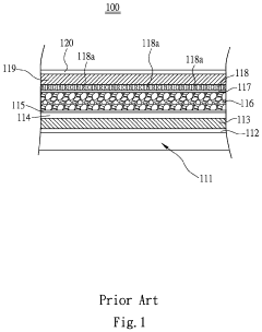
[0031]Micro LEDs are regarded as the next-generation display technology due to its superior properties such as high contrast, high efficiency, high resolution, high response time, etc. Furthermore, a micro LED display device has high color saturation and rapid frame rate and is particularly suitable for next-generation advanced applications (e.g. ultrahigh-definition TVs, micro projectors). An elementary type of micro LED display device only utilizes RGB LEDs to generate a full color image. However, this kind of micro LED display device has disadvantages due to natural material properties of RGB LEDs, such as low efficiency of green LEDs and seriously reduced EQE (External Quantum Efficiency) of red LEDs when LED chip size shrinks down to below 20 μm. Furthermore, owing to the different materials properties of different color LEDs, mismatch in electrical properties occurred thereby resulting in difficulties on integrating these different LEDs. Accordingly, the present disclosure pro...


PUM


Abstract

A micro LED display device includes a micro LED array, a light enhancing layer, a color filter and a polarizer. The micro LED array includes a plurality of micro LEDs, wherein each of the micro LEDs is independently controlled to emit a light. The light enhancing layer is located above the micro LED array, wherein the light enhancing layer includes a plurality of quantum dots. The color filter is located above the light enhancing layer, wherein properties of the light of each of the micro LEDs is converted by each of the quantum dots thereby projecting a plurality of sub-pixel units in the color filter. The polarizer is located above the color filter.

Description

RELATED APPLICATIONS[0001]This application is a continuation of Ser. No. 16 / 136,233, entitled “MICRO LED DISPLAY DEVICE” (now Pub. No. US 2019 / 0245006 A1) filed Sep. 19, 2018, which is herein incorporated by reference.BACKGROUNDTechnical Field[0002]The present disclosure relates to a display device. More particularly, the present disclosure relates to a micro LED display device.Description of Related Art[0003]Recently, a display device has been rapidly developed as an important human-machine interface. A portable electronic device, a computer or a television can represent complicated messages through the display device.[0004]Owing to the demands on the large visible area, compact volume and low energy consumption, a liquid crystal display (LCD) device is getting more popular and has become a mainstream. A conventional LCD device 100 is shown in FIG. 1. The LCD device 100 includes, from bottom to top, a backlight module 111, a first polarizer 112, a first substrate 113, a transistor ...

Claims


Application Information

Patent Timeline
IPC IPC(8): H01L27/15G02B5/20H01L33/50H01L33/58G02B5/30H01L25/075
CPCH01L27/156G02B5/201H01L25/0753H01L33/58G02B5/3025H01L33/507H01L33/44H01L33/502
Inventor TSAI, PING-YUCHEN, CHUNG-CHING
Owner YINGLIGHT TECH