Surgical tool

a surgical tool and tool body technology, applied in the field of surgical tools, can solve the problems of stem displacement or accidental dislocation, femoral head wear, stem displacement or wear, etc., and achieve the effects of high separation force, high mechanical advantage, and control of force applied

Active Publication Date: 2021-06-10
OXFORD UNIV INNOVATION LTD
View PDF0 Cites 0 Cited by
  • Summary
  • Abstract
  • Description
  • Claims
  • Application Information

AI Technical Summary

Benefits of technology

[0024]Preferably, the tool has mirror plane symmetry about an axis which extends transverse to an axis of the crossover joint. The symmetry eliminates shearing effects that may otherwise twist or deform the tool, potentially resulting in unsatisfactory contact with the components to be separated, or undesirable shearing forces. In an embodiment, the crossover component has a cleft therein in which said second handle is supported at said crossover joint.
[0027]The second jaw may include a femoral head grip capable of engaging the underside of a femoral head through a lateral aperture when the tool approaches the head radially and generally perpendicular to a longitudinal axis of a femoral stem to which the femoral head is attached. Preferably the femoral head grip has at least three points at which it can simultaneously engage the femoral head in order to provide a stable and balanced load to the femoral head during separation. The femoral head grip preferably has a generally circular profile. Both of the femoral head grip and the femoral stem grip may be chamfered. This helps the tool seat and centre itself on the components being separated, improving grip and stability.
[0028]It is preferred that the jaws remain relatively parallel during said separation. This can be achieved with the claimed tool as there is more of a translation element than a rotational element to the separation of the jaws and the separation takes place over a very short stroke.
[0030]Safety features may be provided wherein one or more of said first handle, said second handle and said crossbar is provided with a safety endstop to avoid trapping fingers therebetween when a gripping force is applied. The endstop(s) can prevent the handles from being fully closed together.
[0031]The position of the third joint on the second handle is adjustable in order to adjust the mechanical advantage of the tool. This may be achieved using a screw mechanism which can be manually operated to cause the third joint to advance or retreat along the second handle. This adjustment allows a surgeon to position the tool's jaws accurately before applying a gripping force to the handles, to adjust the mechanism to a comfortable working configuration and to control the force applied. Compared to prior art mechanisms, the claimed tool is able to provide a very high mechanical advantage allowing the surgeon to exert extremely high separation forces on the components. Preferably the separating jaws are capable of applying a 7.5 kN force over a 0.3 mm stroke. The mechanical advantage of the tool may amplify the user's grip force by a factor of 20.
[0033]Preferably, in use, the tool is positionable radially and generally perpendicular to a longitudinal axis of a femoral stem. This avoids the difficulty of space constraint near the top of the hip in the axial direction.

Problems solved by technology

Friction, created by the shearing of the wall of a bore in the head as it is pushed onto a trunnion on the stem, causes an interference fit and cold-welding between the two components, which increases during physiological loading.
A problem occurs when the femoral head has become worn or damaged and needs replacing but the stem is still in good condition.
The force required to remove the head often exceeds the force required to move the stem, resulting in unwanted displacement of the stem.
In particular, torsional force on the stem is highly undesirable as that may result in displacement or accidental dislodging of the stem, or even fracture of the femur.
In this situation, also, it may be difficult to remove the trial head from the implanted stem.
Crudely striking the head with an oblique-angled chisel or punch to remove it from the stem risks unwanted forces on the stem as outlined above.
Attempting to twist and pull the head off the stem by hand risks unwanted torsional force on the stem, or the surgeon being unable to apply sufficient force manually.
Those which apply an axial force to the femoral head, away from the stem, are relatively cumbersome and access to the head from the axial direction is difficult.
These tools may not be able to be used at all on smaller patients.
A problem with this type of tool is that force is only applied to one side of the femoral head and damage to the stem may also occur.
Furthermore, the mechanical advantage is fixed and cannot be modified by the surgeon.
Also, since the wedges have to slide over the implant components, the components may be marked or otherwise damaged.
Another disadvantage of known tools is that they may be specialised for a particular design of hip implant and thus not useful for the wide range of hip implants which may be encountered in revision surgery.

Method used


Image

  • Surgical tool
  • Surgical tool
  • Surgical tool

Examples


Embodiment Construction

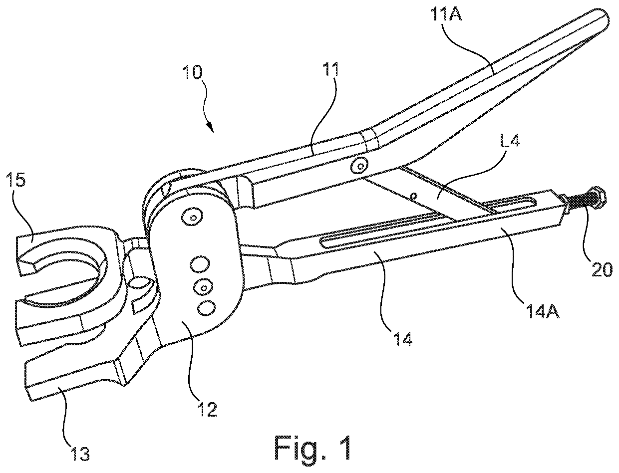
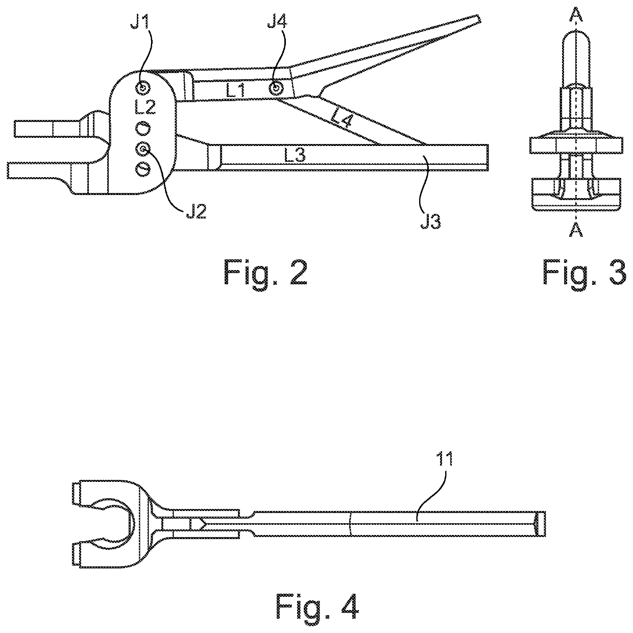
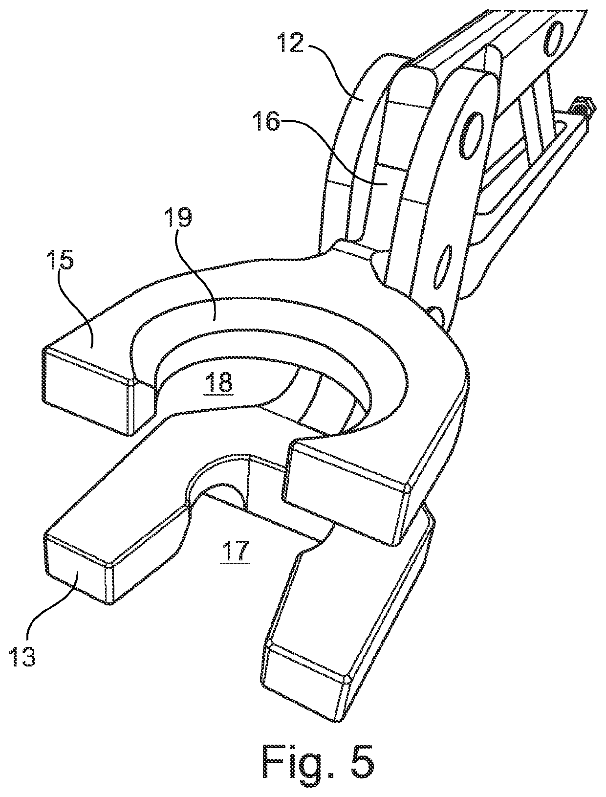
[0055]FIGS. 1-4 show a surgical tool 10 according to one embodiment of the invention, the tool being suitable to separate a femoral head from a femoral stem.

[0056]In general terms, the surgical tool uses a four bar chain and crossover joint to provide a high mechanical advantage, converting a gripping force by the surgeon on two handles into a separating force at two jaws engaging the femoral head and stem.

[0057]A four bar chain arrangement is well known in many hand tools, for example in locking pliers, however it is normally used to provide a clamping or gripping action. In the claimed invention, the opposite is the case in that a separating action is provided.

[0058]The surgical tool 10 comprises a first handle 11, a second handle 14 and a crossbar L4 therebetween. The proximal ends of the handles, proximal of the crossbar L4, form gripping portions 11A, 14A respectively which are suitably sized that a surgeon may grip both gripping portions 11A, 14A simultaneously with one hand a...


PUM


Abstract

A surgical tool for separating two components, for example removing a femoral head from a femoral stem, having a four bar chain whose four bars are a first handle (L1), an crossover component (L2), a second handle (L3) and a crossbar (L4) pivotally connected respectively by: a first joint (J1) between the first handle and the crossover component; a second, crossover joint (J2) between the crossover component and the second handle; a third joint (J3) between the second handle and the crossbar, and a fourth joint (J4) between the crossbar and the first handle, and wherein, upon application of a gripping force to the first and second handles, the first and second jaws separate from one another so as to separate the two components engaged therewith.

Description

[0001]This invention relates to a surgical tool for removing a femoral head from a femoral stem in total hip arthroscopy revision surgery.BACKGROUND[0002]Hip replacement, or arthroplasty, is a surgical procedure in which the damaged or diseased hip joint is replaced by a new prosthetic implant. The procedure is most commonly performed on people between the ages of 60 and 80, generally due to osteoarthritis or in some cases, hip fractures. The purpose of the procedure is primarily to relieve pain and improve the function and mobility of the hip.[0003]The procedure begins with the surgeon making a 15-20 cm incision over the side of the hip through the muscles, after which they remove the diseased bone tissue and cartilage from the hip joint. The head of the femur is removed and the interior of the femur is hollowed and shaped to fit the artificial stem. The head of the femur and the acetabulum are then replaced with two prosthetic parts, with the prosthetic femoral head being joined t...

Claims


Application Information

Patent Timeline
Patent Type & Authority Applications(United States)
IPC IPC(8): A61F2/46
CPCA61F2/4637A61F2/4607A61F2002/3611A61F2002/4628A61F2002/4641A61F2002/30537A61F2002/365A61B17/2804A61F2002/3625
Inventor HUBER, JOHNLIN, DALEWELD, KATHERINEHUBER, CHRISSARRAF, KHALED
Owner OXFORD UNIV INNOVATION LTD
Why Eureka
Try Eureka