Timing calibration using internal radiation and external radiation source in time of flight positron emission tomography

a technology of positron emission tomography and internal radiation, which is applied in the direction of tomography, x/gamma/cosmic radiation measurement, instruments, etc., can solve the problems of difficult handling, inability to determine three unknowns from two equations, and inapplicability, so as to reduce the required number of counts and achieve reasonable acquisition time for internal radiation.

Active Publication Date: 2021-07-01
CANON MEDICAL SYST COPRPORATION
View PDF2 Cites 6 Cited by
  • Summary
  • Abstract
  • Description
  • Claims
  • Application Information

AI Technical Summary

Benefits of technology

[0034]Using a single stationary limited-extent external source eliminates the major drawbacks of the external source methods in the conventional TOF PET methods. Furthermore, dividing the process into two steps allows to significantly reduce the total amount of data required for the internal radiation process, thereby eliminating the major drawback of the internal radiation methods in the conventional TOF PET.
[0035]The number of counts required for the internal radiation step is significantly reduced for two reasons. First, by determining a relative offset in the external source step, the offsets determined in the internal radiation step are only “processing unit offset”. This means that all of the counts from all of the scintillator crystals in a processing unit can be aggregated, thereby reducing the acquisition time. As an example, if the scintillator array in one processing unit has 10×10=100 crystals, then the number of counts required to achieve the desired accuracy at the processing unit level is reduced by a factor of 100 compared to the number of counts to achieve the same accuracy in the external source step at the crystal level. In addition, by pre-correcting the internal radiation timing data using the results from the external source step, the width of the distributions in the internal radiation data are significantly reduced. This effect is even larger when the relative offset correction obtained in the external source step includes walk correction, and, in particular, non-linear walk correction.
[0037]Correcting for walk before the ‘internal radiation’ step also allows us to use all of the counts acquired, rather than limiting the analysis to events in narrow energy windows (as was done in the prior-art), as shown in FIG. 16. This further reduces the required acquisition time.
[0038]FIG. 8A shows an internal radiation timing distribution before applying the relative offset correction obtained from the external source, and FIG. 8B shows the distribution for the same data after applying the timing corrections from the first step (including non-linear walk correction). In this case, the widths of the timing distributions are reduced by a factor of more than 2. To achieve the same statistical uncertainty in the processing unit offset, the effect of this reduction in distribution width is roughly equivalent to increasing the number of counts by more than a factor of 4. Therefore, by separating the process into two steps, and pre-correcting the data in the second step before performing the calculations, the amount of data required (or the acquisition time) for the internal radiation step has been reduced by approximately a factor of 100×4=400, in the example provided (compared to the case of using internal radiation at the crystal level and without first pre-correcting the data). This takes the acquisition time from several hours in the case of using internal radiation for the entire calibration to on the order of a minute for the method described here, and this was done without the use of large or moving external sources.
[0043]Advantages include reducing the need for large limited extent source, source movement, or multiple sources. Small limited-extent source is easier to handle and shield, and less costly to replace. Furthermore, processing unit offset can be re-calibrated periodically using only internal radiation.

Problems solved by technology

Due to unavoidable manufacturing tolerances such as differences in cable lengths or timing response of different photo sensors in the detectors, calibration is required to ensure sufficient accuracy of the measured time differences.
However, since PET scanners typically contain tens of thousands of detector elements, and the number of LORs is on the order of hundreds of millions, this approach is not practical.
Determining three unknowns from two equations is clearly impossible.
This indicates a substantial problem with performing a timing calibration with a single limited-extent source in a single fixed position.
The drawbacks of the method shown in FIG. 6A are that the phantom itself might weigh 20 kg, making it difficult to handle, and the phantom requires very heavy shielding (for example, approximately 150 kg of lead) to protect staff and patients when the phantom is not in use.
The complexity, cost, and maintenance of the mechanism which provides the movement of the source are drawbacks of this method.
The large size of the annihilation target is a drawback to this method because it can be difficult to handle.
The large size can also make storage, when not in use, inconvenient.
First, the phantom is rather heavy, and can be difficult to handle.
Second, due to attenuation and the low efficiency for scatter of 511 keV gamma rays, very few of the gamma rays that are emitted from the source are actually available to provide one-to-many coupling, so the data acquisition can be long and the convergence of iterative methods for estimating the offsets can be slow.
Additionally, the uncertainty in the scatter location reduces the accuracy, particularly for the timing resolution (-200 ps) that is achievable in state-of-the-art systems.
In addition to suffering from long data acquisition times, limiting the LORs to adjacent modules has another severe drawback.
Therefore, the method is limited to calibration of blocks which are generally less than ˜20 mm across.
For methods using external radiation sources, either the phantoms are large and difficult to handle or they require complex mechanical motion.
On the other hand, methods using internal radiation are generally very slow.

Method used


Image

  • Timing calibration using internal radiation and external radiation source in time of flight positron emission tomography
  • Timing calibration using internal radiation and external radiation source in time of flight positron emission tomography
  • Timing calibration using internal radiation and external radiation source in time of flight positron emission tomography

Examples


Embodiment Construction

[0068]Reference throughout this specification to “one embodiment” or “an embodiment” means that a particular feature, structure, material, or characteristic described in connection with the embodiment is included in at least one embodiment of the application, but do not denote that they are present in every embodiment.

[0069]Thus, the appearances of the phrases “in one embodiment” or “in an embodiment” in various places throughout this specification are not necessarily referring to the same embodiment of the application. Furthermore, the particular features, structures, materials, or characteristics may be combined in any suitable manner in one or more embodiments.

[0070]A PET scanner in the present embodiments may have different electronics architectures. Non-limiting example layouts are shown in FIG. 9 and FIG. 10, where:

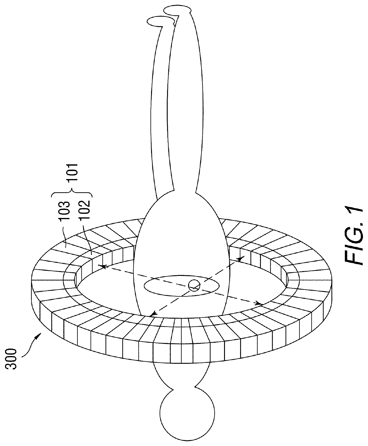
[0071]PET scanner: a whole scanner, usually in the form of a ring.

[0072]Region: a relatively large part of the scanner, such as a quadrant, which consists of advanc...


PUM


Abstract

A method and system for providing improved timing calibration information for use with apparatuses performing Time of Flight Positron Emission Tomography scans. Relative timing offset, including timing walk, within a set of processing units in the scanner are obtained and corrected using a stationary limited extent positron-emitting source, and timing offset between the set of processing units is calibrated using an internal radiation source, for performing calibration.

Description

[0001]This application is based on and claims the benefit of and priority to U.S. Provisional Patent Application No. 62 / 955,270, entitled “TIMING CALIBRATION USING LUTETIUM BACKGROUND RADIATION AND EXTERNAL RADIATION SOURCE”, filed on Dec. 30, 2019, the entire contents of which are herein incorporated by reference.BACKGROUNDTechnical Field[0002]The disclosure relates to a method and system for providing improved timing calibration information for use with apparatuses for performing Time of Flight (TOF) positron emission tomography (PET) scans, and, in one embodiment, to a TOF PET scan using an internal radiation source (e.g., a lutetium radiation source) in conjunction with a stationary limited extent annihilation radiation source (e.g., a positron emitting Ge68 / F18-FDG line source) for performing calibration thereof.Description of the Related Art[0003]In PET, images of a living body are created. PET scanners produce images that illustrate various biological processes and functions....

Claims


Application Information

Patent Timeline
Patent Type & Authority Applications(United States)
IPC IPC(8): G01T7/00G01T1/29
CPCG01T7/005G01T1/2985A61B6/037A61B6/5258
Inventor LI, XIAOLIQIANG, YIBURR, KENT C.PENG, PENG
Owner CANON MEDICAL SYST COPRPORATION
Why Eureka
Try Eureka