
Buffer pre-activation for electrochromic device

a buffer and electrochromic technology, applied in the field of electrochromic devices, can solve the problems of inability to adequately return to a predetermined state, undesirable oxidation or reduction of the electrochromic medium, etc., and achieve the elimination or reduction of the disadvantages and problems associated with the electrochromic devise incorporating buffers in the pas

Pending Publication Date: 2021-08-05
GENTEX CORP
View PDF4 Cites 0 Cited by
  • Summary
  • Abstract
  • Description
  • Claims
  • Application Information

AI Technical Summary

Benefits of technology

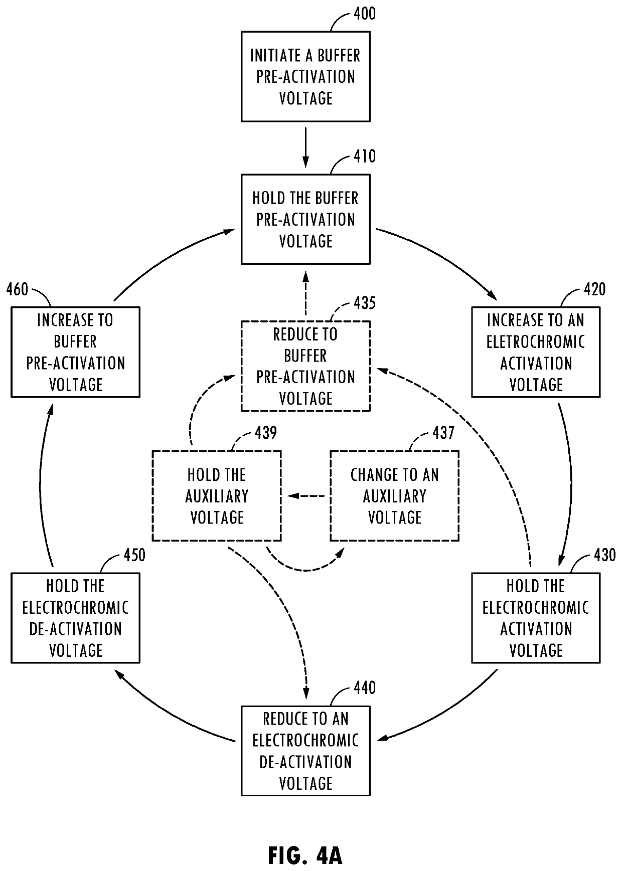
The present patent aims to improve the performance of electrochromic devices by eliminating or reducing the problems associated with incorporating buffers in the past. The invention provides a faster and more responsive electrochromic device that allows the buffer to fully activate the solution prior to a desired change in device transmittance, resulting in increased speed of transmittance change without increased consumption of electrical current.

Problems solved by technology

However, during normal operation, electrochromic media sometimes do not adequately return to a predetermined state.
This oxidation or reduction of the electrochromic medium may be undesirable.
This undesirable oxidation or reduction may be caused by undesirable electrochromic medium impurities, exposure of the electrophilic medium to the external atmosphere, and / or long-term weathering of the electrochromic device.
However, when the electrical potential is applied to the electrochromic solution, these buffers may slow down the darkening of an electrochromic device.
When an imbalance of anodic oxidation and cathodic reduction occurs, an undesirable electrochromic medium coloration may manifest in the electrochromic device.
Further, the fourth voltage may not be operable to substantially activate the electrochromic materials.

Method used


Image

  • Buffer pre-activation for electrochromic device
  • Buffer pre-activation for electrochromic device
  • Buffer pre-activation for electrochromic device

Examples


Embodiment Construction

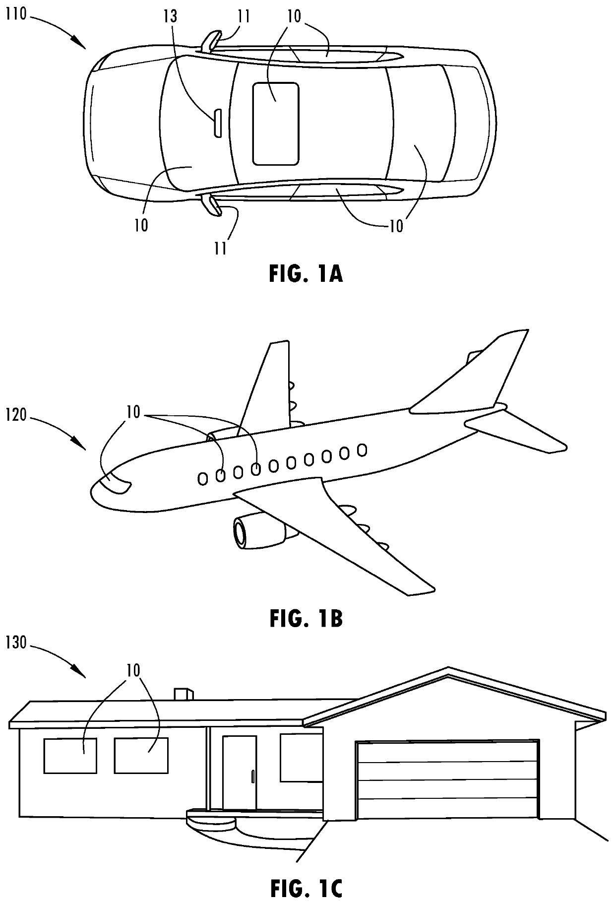
[0031]For the purposes of description herein, it is to be understood that the specific devices and processes illustrated in the attached drawings and described in this disclosure are simply exemplary embodiments of the inventive concepts defined in the appended claims. Hence, specific characteristics relating the embodiments disclosed herein are not to be considered as limiting, unless the claims expressly state otherwise.

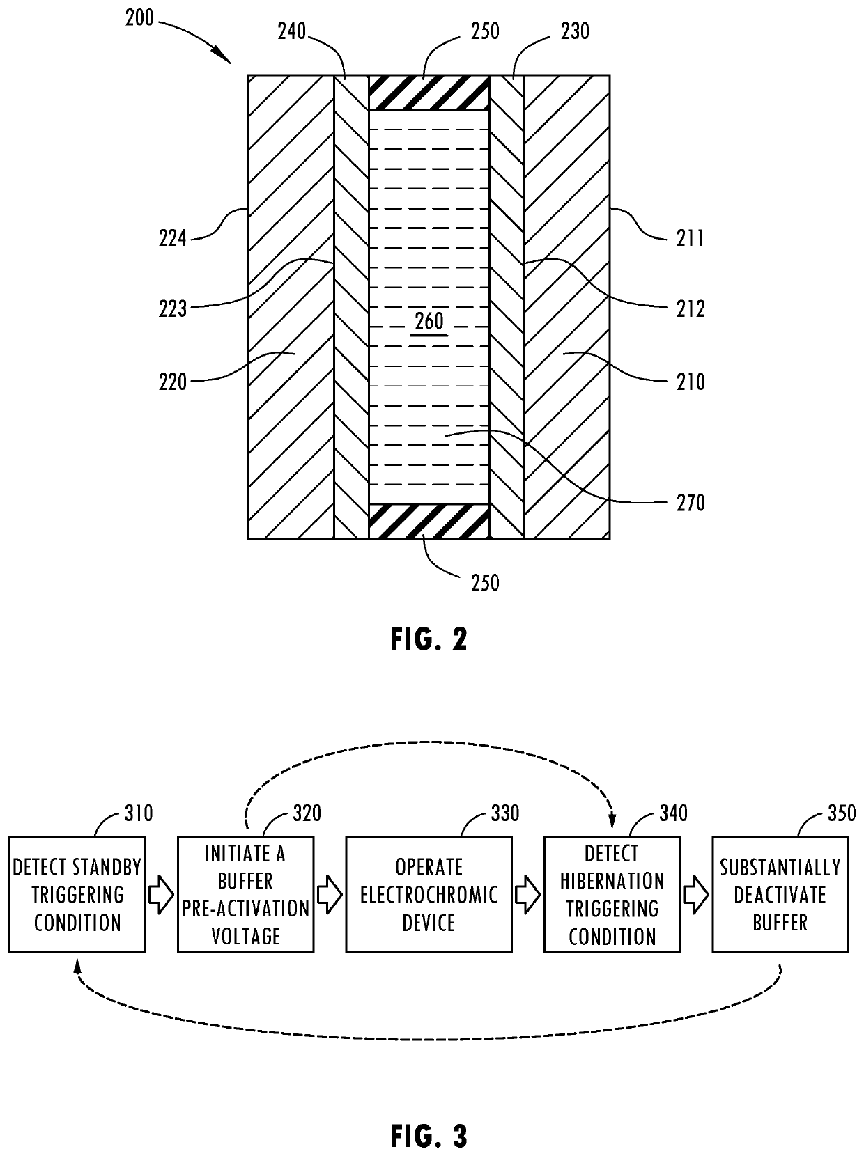
[0032]The present disclosure is directed to an electrochromic device with and / or method for, buffer pre-activation. Electrochromic devices generally comprise an electrochromic medium, the electrochromic medium may contain a solvent, one or more electrochromic materials, and / or a buffer. The buffer may be a redox buffer. Generally, to act as a redox buffer, a buffer may exhibit a redox potential in the range bound by an anodic oxidation potential and a cathodic reduction potential of the electrochromic materials. Accordingly, the buffer may be activated at a lower e...


PUM


Abstract

An electrochromic device, system using, and method for, which may pre-activate a buffer is disclosed. The electrochromic device may comprise a first substrate, a second substrate, a first electrode, a second electrode, and an electrochromic medium. The second substate may be disposed in apart relationship with the first substrate. The first and second electrodes may be associated with the first and second substrates, respectively. The electrochromic medium may be disposed between the first and second electrodes. Further, the electrochromic medium may comprise electrochromic materials and a redox buffer. Each of the electrochromic materials and the buffer may be operable between activated and deactivated states. The electrochromic device may be configured to apply a voltage to substantially pre-activate the buffer and hold the buffer in this state prior to substantially activating the electrochromic materials, thereby decreasing the response time of the electrochromic device upon activation.

Description

CROSS-REFERENCE TO RELATED APPLICATIONS[0001]This application claims priority under 35 U.S.C. § 119(e) to U.S. Provisional Application No. 62 / 969,359 filed on Feb. 3, 2020, entitled “BUFFER PRE-ACTIVATION FOR ELECTROCHROMIC DEVICE,” the disclosure of which is hereby incorporated by reference in its entirety.FIELD OF INVENTION[0002]The present invention relates in general to electrochromic devices and, more particularly, to operating electrochromic devices having an electrochromic solution comprising one or more buffer and one or more electrochromic material.BACKGROUND OF INVENTION[0003]Electrochromic devices have been well known for many years. When a sufficient electrical potential is applied across a pair of electrodes, an electrochromic medium, disposed between the electrodes, may become activated, changing its color and / or light transmissivity. Taking advantage of this, devices such as dimmable mirrors and windows have become increasingly popular the automotive and aviation indu...

Claims


Application Information

Patent Timeline
IPC IPC(8): G02F1/155G02F1/1514G02F1/153
CPCG02F1/155G02F1/1533G02F1/1514E06B9/24G02F1/163E06B2009/2464
Inventor SAENGER NAYVER, MARIO F.ANDERSON, JOHN S.NEUMAN, GEORGE A.
Owner GENTEX CORP
Learn More