Time-of-flight mass spectrometer

Active Publication Date: 2021-08-12
SHIMADZU CORP
View PDF0 Cites 0 Cited by
  • Summary
  • Abstract
  • Description
  • Claims
  • Application Information

AI Technical Summary

Benefits of technology

[0026]According to the invention, the running costs can be reduced by setting the target temperature low when the ambient temperature is low.
[0027]Further, according to the invention, even in a case where the heater is continuously driven at the maximum output due to a failure or the like, the risk of fire is low and the safety can be improved.
[0028]Further, according to the invention, even in a case where the device is applied to a wide range of ambient temperatures, the device performance can be sufficiently exhibited by using a low output heater without adjusting the ambient temperature by a

Problems solved by technology

Therefore, when the temperature (ambient temperature) in the vicinity of the flight tube is changed, the flight tube thermally expands or contract

Method used


Image

  • Time-of-flight mass spectrometer
  • Time-of-flight mass spectrometer

Examples


Example

[0033]1. Overall Configuration of Liquid Chromatograph Mass Spectrometer

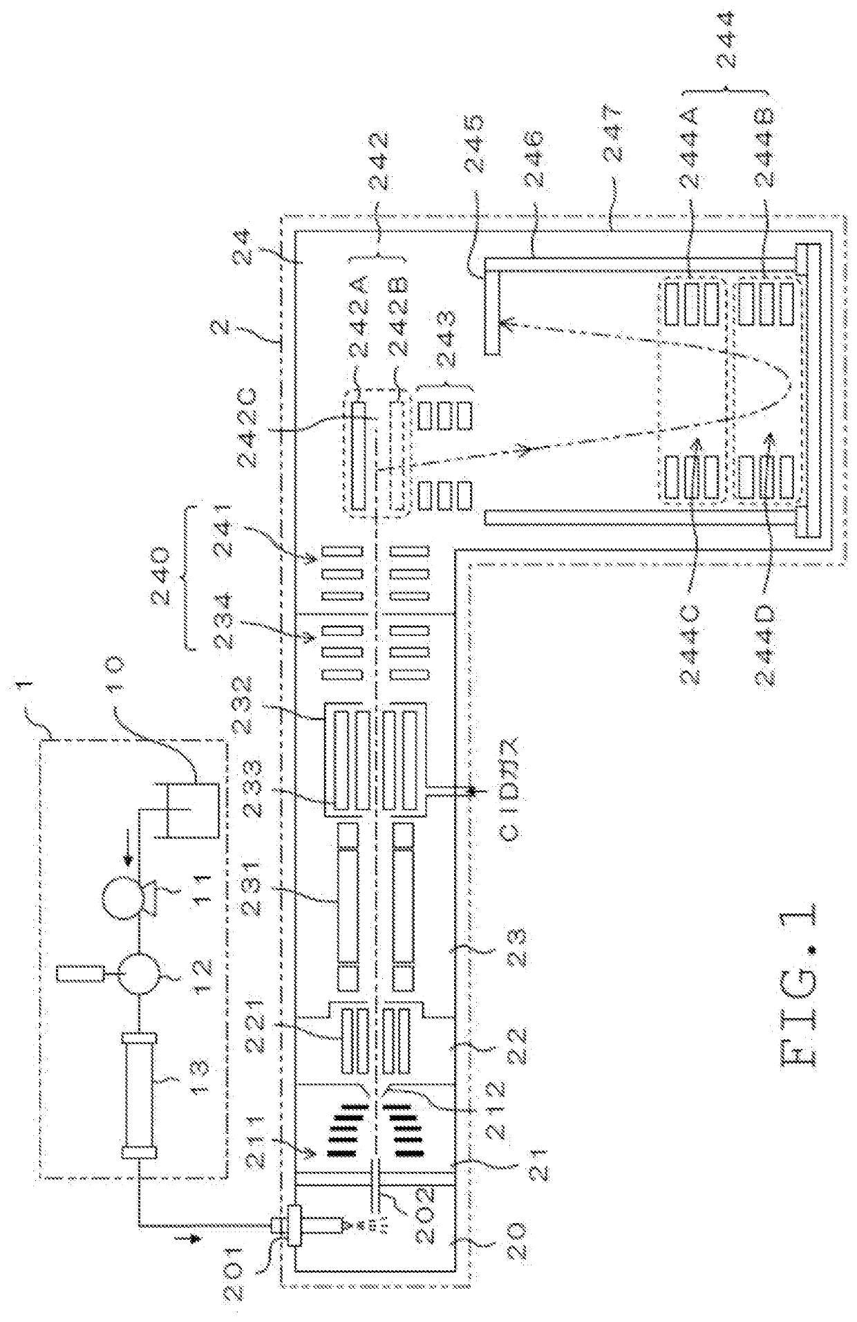
[0034]FIG. 1 is a schematic diagram illustrating a configuration example of a liquid chromatograph mass spectrometer including a time-of-flight mass spectrometer according to an embodiment of the invention. The liquid chromatograph mass spectrometer includes a liquid chromatograph unit 1 and a mass spectrometer unit 2.

[0035]The liquid chromatograph unit 1 includes a mobile phase container 10, a pump 11, an injector 12, a column 13, and the like. A mobile phase is stored in the mobile phase container 10. The pump 11 sends out the mobile phase in the mobile phase container 10 to the injector 12. In the injector 12, a predetermined amount of sample is injected into the mobile phase from the mobile phase container 10. The mobile phase into which the sample is injected is introduced into the column 13, and respective components in the sample are separated in the course of passing through the column 13. The respective...


PUM


Abstract

A flight tube 246 is hollow, and ions emitted from an ion emission unit are introduced into the flight tube 246. A reflectron 244 is provided in the flight tube 246, and is configured by coaxially arranging a plurality of annular electrodes 244A and 244B. A vacuum vessel 247A that becomes in a vacuum state during analysis is formed in the vacuum chamber 247, and the flight tube 246 is provided in the vacuum vessel 247A. A temperature control mechanism 248 controls a temperature of the flight tube 246. An ambient temperature sensor 250 detects an ambient temperature outside the vacuum chamber 247. A target temperature of the temperature control mechanism 248 is set on the basis of the ambient temperature detected by the ambient temperature sensor 250.

Description

TECHNICAL FIELD[0001]The present invention relates to a time-of-flight mass spectrometer including a hollow flight tube into which ions emitted from an ion emission unit are introduced.BACKGROUND ART[0002]In a time-of-flight mass spectrometer (TOFMS), ions to be analyzed are emitted from an ion emission unit, and the ions fly in a hollow flight tube and then are detected by a detector. As a result, the time of flight of the ion until the ion reaches the detector is measured, and the mass-to-charge ratio m / z of the ion is calculated on the basis of the time of flight (refer to, for example, Patent Document 1).[0003]The flight tube is formed of metal. Therefore, when the temperature (ambient temperature) in the vicinity of the flight tube is changed, the flight tube thermally expands or contracts to cause fluctuation of the time of flight of the ion in the flight tube, and thereby the measurement accuracy becomes poor, which is a problem.[0004]Therefore, by controlling the temperature...

Claims


Application Information

Patent Timeline
IPC IPC(8): H01J49/40H01J49/04H01J49/00
CPCH01J49/405H01J49/0009H01J49/0486H01J49/40G01N27/62
Inventor KUDO, TOMOYA
Owner SHIMADZU CORP
Why Eureka
Try Eureka