Processing system, evacuating system for processing system, low-pressure CVD system, and evacuating system and trapping device for low-pressure CVD system

Inactive Publication Date: 2005-11-22
TOKYO ELECTRON LTD
View PDF16 Cites 64 Cited by
  • Summary
  • Abstract
  • Description
  • Claims
  • Application Information

AI Technical Summary

Benefits of technology

[0016]The present invention has been made in view of the foregoing problems and it is therefore an object of the present invention to provide a processing system and an evacuating system capable of ensuring the stable operation of a vacuum

Problems solved by technology

However, since those copper compounds are solid at an ordinary temperature, those copper compounds are difficult to supply in gases into a processing chamber.
CpCuTEP has a very low vapor pressure of 0.01 torr at 80° C. and hence it is difficult to supply CpCuTEP at a sufficiently high partial pressure to the processing chamber when depositing a film.
This characteristic of Cu(I)hfacTMVS is a problem with the evacuating system for a low-pressure CVD process.
Unused Cu(I)hfacTMVS sucked from the processing chamber condenses in the vacuum pump if the temperature in the vacuum pump is low and will caus

Method used


Image

  • Processing system, evacuating system for processing system, low-pressure CVD system, and evacuating system and trapping device for low-pressure CVD system
  • Processing system, evacuating system for processing system, low-pressure CVD system, and evacuating system and trapping device for low-pressure CVD system
  • Processing system, evacuating system for processing system, low-pressure CVD system, and evacuating system and trapping device for low-pressure CVD system

Examples


Example

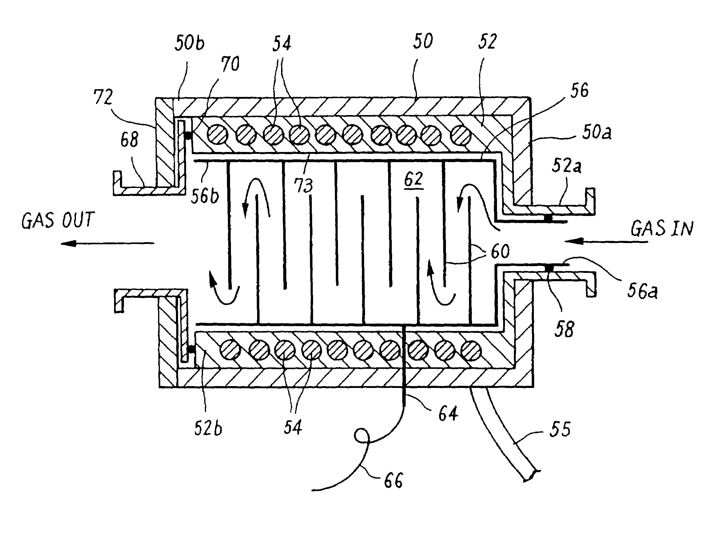
[0078]FIG. 4 shows a trapping device in a first embodiment according to the present invention suitable for use as the high-temperature trapping device 28.

[0079]Referring to FIG. 4, a housing 50 is made of a heat-insulating material, such as silicone rubber, in the shape of, for example, a rectangular cylinder. An end wall 50a provided with a gas inlet opening is formed at a first end (right end as viewed in FIG. 4). A second end (the other end) 50b of the housing 50 is open to receive a trapping unit therein through the second end 50b.

[0080]A heater body 52 made of a heat-conducting material, such as a stainless steel, in the shape of a rectangular cylinder similar to and smaller by one size than the housing 50 is fitted in the housing 50. A tubular projection 52a is formed at a first end (right end as viewed in FIG. 4) of the heater body 52. The tubular projection 52a projects axially outside through the opening formed in the end wall 50a of the housing 50 so as to define an inlet...

Example

[0093]FIG. 5 shows a trapping device in a second embodiment according to the present invention. This trapping device is similar in construction and function to the trapping device in the first embodiment except that the inner construction of a trap body 56 thereof is a modification of that of the trap body 56 of the trapping device in the first embodiment.

[0094]Referring to FIG. 5, a plurality of trapping plates 74 are arranged axially at predetermined stepped intervals in the trap body 56. The four sides of each trapping plate 74 are joined closely to the inner surfaces of the four side walls of the trap body 56. Intervals between the trapping plates 74 decreases gradually from the inlet side toward the outlet side.

[0095]As shown in FIG. 6, each trapping plate 74 is provided with a plurality of openings 74a, the diameter of the holes 74a of the trapping plate 74 nearer to the inlet side is greater than that of the holes 74a of the trapping plate 74 nearer to the outlet side. The tr...

Example

[0101]FIGS. 7 to 9 show a trapping device in a third embodiment according to the present invention suitable for use as the low-temperature trapping device 30, in which FIG. 7 is a longitudinal sectional view, FIG. 8 is a top view and FIG. 9 is a cross-sectional view.

[0102]This trapping device has a housing 80 formed of a heat conducting material, such as a stainless steel in the shape of a bottomed rectangular cylinder. The housing 80 has a top wall serving as a top cover 81 and provided in its central part with an inlet opening 82, and a side wall provided in its lower part with an outlet opening 84 and a chemical liquid drain port 86.

[0103]The housing 80 has four side walls 80a, 80b, 80c and 80d. Water passages 88 and 90 for passing temperature regulating water are formed in the opposite side walls 80a and 80c, respectively, as shown in FIG. 9. The top cover 81 of the housing 80 is provided with an water inlet port 92 connected to the water passage 88 formed in the side wall 80a, ...


PUM

PropertyMeasurementUnit
Temperatureaaaaaaaaaa
Pressureaaaaaaaaaa

Abstract

An object of the present invention is to ensure the stable operation of a vacuum pump for discharging an unused source gas and reaction byproduct gases from a low-pressure processing chamber, to recover the reaction byproducts efficiently for the effective utilization of resources and reduction of running costs. A low-pressure CVD system has a processing vessel (10) for carrying out a low-pressure CVD process for forming a copper film, a source gas supply unit (12) for supplying an organic copper compound as a source gas, such as Cu(I)hfacTMVS, into the processing vessel (10), and an evacuating system (14) for evacuating the processing vessel (10). The evacuating system (14) includes a vacuum pump (26), a high-temperature trapping device (28) disposed above the vacuum pump (26) with respect to the flowing direction of a gas, and a low-temperature trapping device (30) disposed below the vacuum pump with respect to the flowing direction of a gas. The high-temperature trapping device (28) decomposes the unused Cu(I)hfacTMVS contained in a gas sucked out of the processing vessel (10) to trap metallic copper. The low-temperature trapping device traps Cu(II)(hfac)2 produced as a reaction byproduct.

Description

[0001]This is a division of application Ser. No. 09 / 523,557 filed Mar. 10, 2000 now abandoned, which is incorporated herein by reference.BACKGROUND OF THE INVENTION[0002]1. Field of the Invention[0003]The present invention relates to a system that uses gases in a microprocess for fabricating semiconductor devices. More specifically, the present invention relates to a processing system of a chemical reaction type, typically, a low-pressure CVD system, and an evacuating system and a trapping device which can be used in combination with a processing system of this kind.[0004]2. Description of the Related Art[0005]Multilevel wiring structures have been used generally in recent years. The progressive increase in device density requires reduction in size of contact holes for connecting metal wiring lines in different wiring layers. Consequently, the aspect ratio (=(Depth of hole) / (Width of hole)) of contact holes increases accordingly. The enhancement of the operating speed of the individ...

Claims


Application Information

Patent Timeline
IPC IPC(8): C23C16/44C23C16/18B01D53/64C23C16/455H01L21/285H01L21/31H01L21/3205H01L23/52
CPCC23C16/18C23C16/4412C23C16/45593H01L21/28556Y02C20/30Y10S55/15Y02P70/50C23C16/4408
Inventor YAMASAKI, HIDEAKIKAWANO, YUMIKOKUBO, KENICHIARIMA, SUSUMU
Owner TOKYO ELECTRON LTD
Why Eureka
Try Eureka