Vapor compression refrigeration system and method of operating such a system

Pending Publication Date: 2021-08-19
EPTA
View PDF0 Cites 2 Cited by
  • Summary
  • Abstract
  • Description
  • Claims
  • Application Information

AI Technical Summary

Benefits of technology

The present invention provides a vapor compression refrigeration system that can operate in a transcritical mode and manage criticalities associated with refrigerant pressure increases without increasing safety pressure of system components or requiring external condensing units. It is simple to manufacture, reliable, and operatively simple to manage.

Problems solved by technology

One of the issues following the introduction of refrigeration systems capable of operating in a transcritical mode, characterized by the use of R744 refrigerant (CO2), is the increase in operating pressures.
Therefore, one of the issues of this type of plants, is maintenance of refrigerant inside the circuits in the event of interruption of the normal refrigeration cycle, due, for example, to a black-out or deriving from the need to disconnect the system for maintenance activities.
When the issue that caused the shutdown is solved, the system may be lacking the necessary quantity of refrigerant for correct restart or operation thereof.
The component of the refrigeration system most affected by this issue is the main liquid receiver placed downstream of the gas cooler, due to the large quantity of refrigerant in liquid state stored therein.
Both solutions are effective but have side effects.
An increase in safety pressure of the system components involves, in fact, an increase in plant costs, as well as maintenance difficulties, due to the difficulty to find different components with higher safety pressures and to the increase in the skills required to maintenance personnel in the event of intervention on the circuit.
However, they are dangerous, especially in maintenance situations in which an open flame for brazing and welding is commonly used.
Both solutions involve using a refrigerant, which is different from the one used in the main refrigerant circuit, thus increasing maintenance complexity.

Method used


Image

  • Vapor compression refrigeration system and method of operating such a system
  • Vapor compression refrigeration system and method of operating such a system
  • Vapor compression refrigeration system and method of operating such a system

Examples


Embodiment Construction

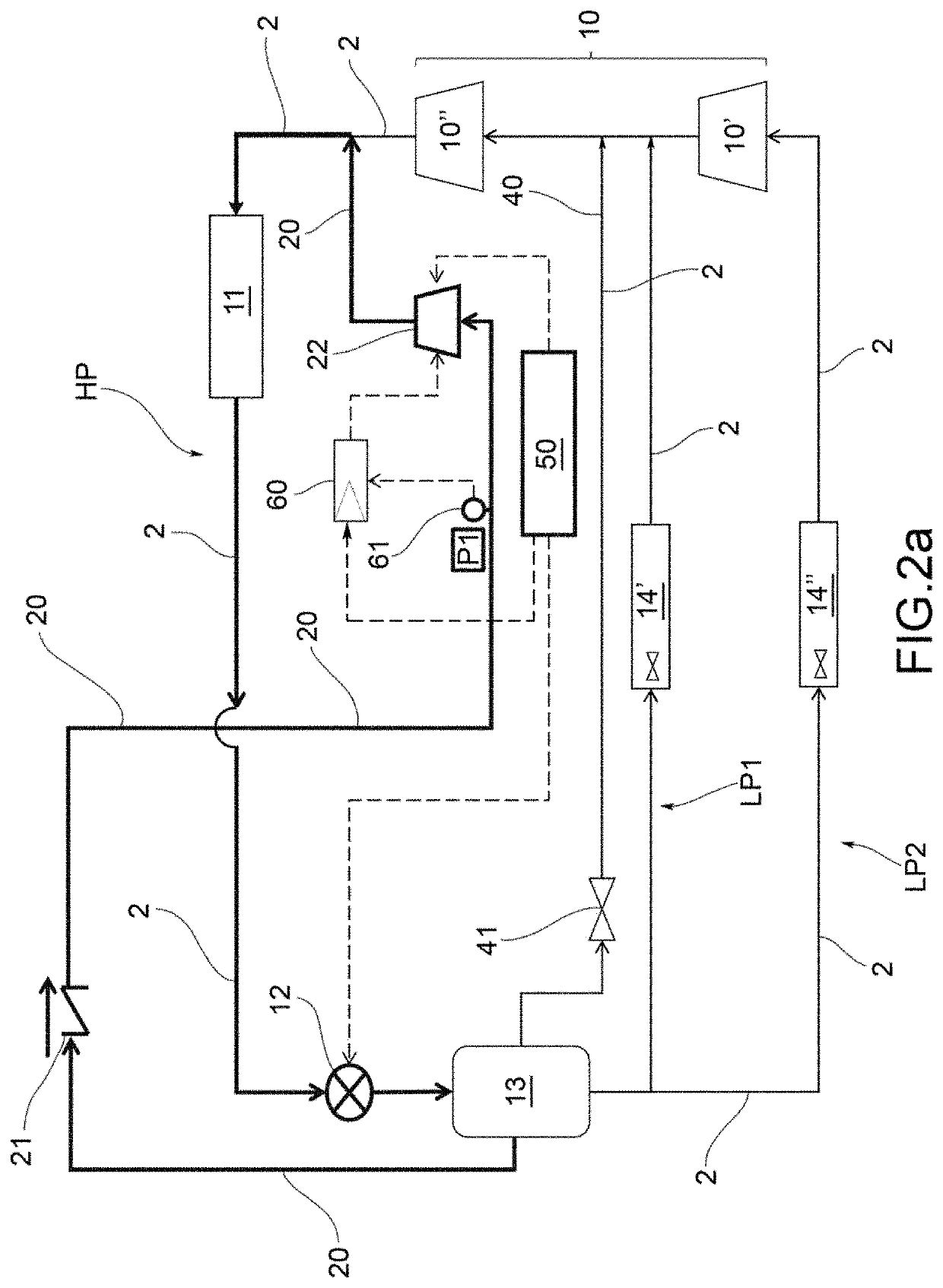
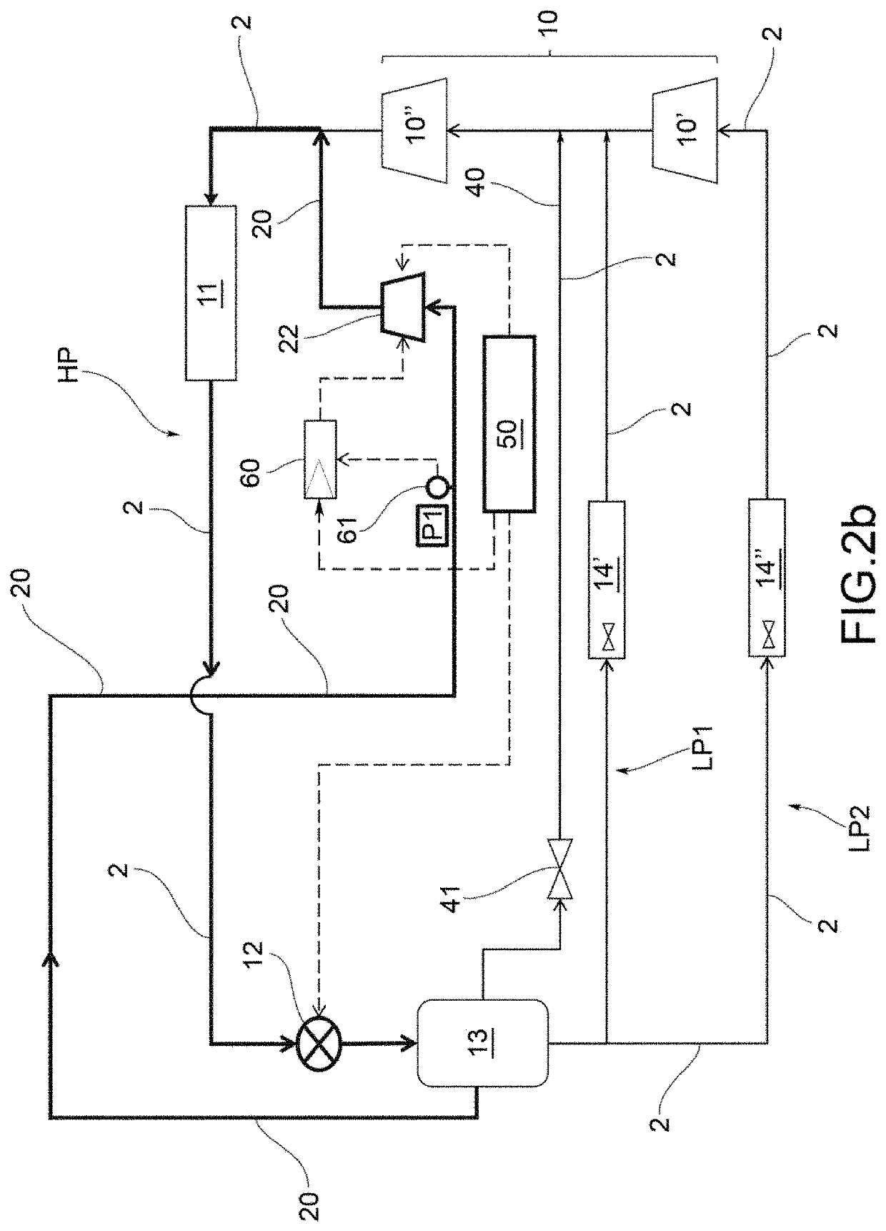
[0031]With reference to the accompanying Figures, reference numeral 1 indicates a refrigeration system according to the present invention.

[0032]The refrigeration system 1 operates according to a vapor compression cycle and is capable of operating both in a transcritical mode as well as in a subcritical mode.

[0033]Preferably, the refrigeration system uses R744 (CO2) as refrigerant fluid. Alternatively, the refrigeration system may use as refrigerant a mixture of transcritical refrigerants with low or very low Global Warming Potential (GWP), possibly containing CO2. A refrigeration system is said to be transcritical if it operates with pressures which exceed the critical pressure Pc of the working fluid. The peculiarity of thermodynamic cycles is that there is no phase transition from gas to liquid in at least one of the heat exchange processes. In that section of the plant the fluid behaves like a dense gas.

[0034]According to a general embodiment of the present invention, the refrige...


PUM


Abstract

A vapor compression refrigeration system has a main refrigerant circuit having a primary compressor group, a gas cooler or condenser, an expansion device, a liquid receiver, and at least one evaporator. An emergency circulation duct fluidically connects the liquid receiver to the main circuit to allow a flow of refrigerant from the liquid receiver to the gas cooler. An emergency compressor group in the emergency circulation duct is activatable when pressure inside the liquid receiver or in the duct upstream of the emergency compressor group meets or exceeds a predefined emergency pressure threshold. An uninterruptible power supply powers the emergency compressor group and expansion device during a shutdown of the refrigeration system. When pressure inside the liquid receiver or in the duct upstream of the emergency compressor group equals or exceeds the predefined emergency pressure threshold, an emergency circulation of refrigerant fluid is activated through the emergency circulation duct.

Description

CROSS-REFERENCE TO RELATED APPLICATION[0001]This application claims priority to and benefit of Italian Patent Application No. 102020000003019, filed Feb. 14, 2020, the contents of which are incorporated by reference in their entirety.FIELD OF THE INVENTION[0002]The present invention relates to a vapor compression refrigeration system and to a method of operating such a system.[0003]The refrigeration system and the operating method according to the present invention find particular application in the commercial and industrial refrigeration field.[0004]The refrigeration system of the present invention is capable of operating both in subcritical mode as well as in transcritical mode, according to the needs of the refrigeration system. Preferably, R744 refrigerant (CO2) is used as refrigerant. The refrigeration system may be of the booster or non-booster type.BACKGROUND OF THE INVENTION[0005]One of the issues following the introduction of refrigeration systems capable of operating in a ...

Claims


Application Information

Patent Timeline
IPC IPC(8): F25B6/02F25B39/00F25B5/00F25B41/22F25B41/34F25B49/02
CPCF25B6/02F25B39/00F25B5/00F25B41/22F25B41/34F25B2700/19F25B2400/0401F25B2400/0403F25B2400/075F25B2500/27F25B2600/2501F25B49/02F25B1/10F25B5/02F25B2309/06F25B2400/0409F25B2400/16F25B2600/2523F25B41/24F25B2500/07Y02B30/70F25B27/00F24F11/32
Inventor CAVALLERI, PAOLODE BONA, MARIOBORTOLUZZI, DAVIDEMAZZOLA, DANIELE
Owner EPTA
Why Eureka
Try Eureka