Rotor blade for a wind turbine and rotor blade tip

a technology of rotor blade and wind turbine, which is applied in the direction of wind turbines, wind turbines with parallel air flow, motors, etc., can solve the problems of limited drainage bore diameter, mechanical damage the evaporation of condensed water in the interior of the rotor blade, so as to achieve good aerodynamic properties and high power. , the effect of effective aerodynamic profil

Active Publication Date: 2021-09-02
NORDEX ENERGY SE & CO KG
View PDF0 Cites 0 Cited by
  • Summary
  • Abstract
  • Description
  • Claims
  • Application Information

AI Technical Summary

Benefits of technology

[0010]According to one embodiment, the drainage bore is formed in such a way that it is accessible only from the suction side. This has the advantage that the profile trailing edge of the rotor blade tip (rear edge), in contrast to solutions known from the prior art, has a closed, continuous contour. This makes possible a particularly effective aerodynamic profile on the rotor blade tip and makes a considerable positive contribution to the aerodynamic properties of the rotor blade tip and thus of the rotor blade, with the acoustic properties, in particular, being optimized. In particular, the trailing edge of the blade tip may have a particular slender configuration. It is also possible for the wind turbine, having such a rotor blade, to be operated in a mode associated with particularly high power.
[0011]According to one embodiment, the drainage bore, in a straight extension of its bore central axis, is freely accessible from the outside. This contributes, analogously to above, to making maintenance tasks at the bore possible in a simple manner. In particular, a bore clogged with dirt can easily be drilled out again. The bore is consequently directly accessible from the outside for mainte

Problems solved by technology

One problem exists for example with lightning strikes, in which the briefly high current can lead to abrupt evaporation of the condensed water in the interior of the rotor blade.
The vapor pressure built up by the evaporation can cause mechanical damage in the interior of the rotor blade.
Consequently, the diameter of the drainage bore is limited, with the disadvantage that, in the blade region in front of

Method used


Image

  • Rotor blade for a wind turbine and rotor blade tip
  • Rotor blade for a wind turbine and rotor blade tip
  • Rotor blade for a wind turbine and rotor blade tip

Examples


Embodiment Construction

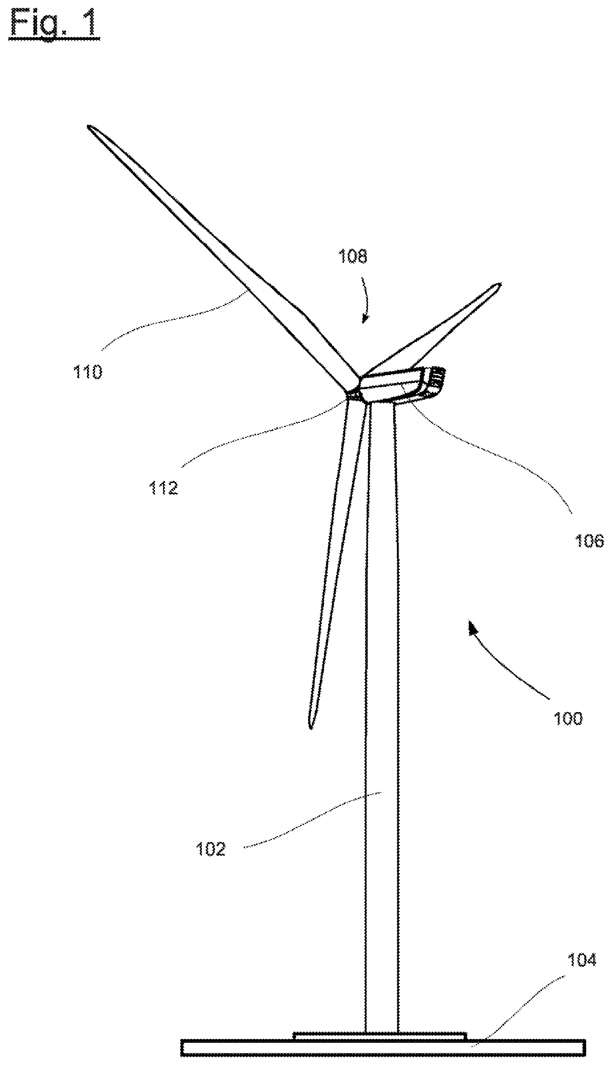
[0026]FIG. 1 is a schematic of a wind turbine 100. The wind turbine 100 has a tower 102 fixed on a base by a foundation 104. A nacelle 106 is mounted rotatably on an end of the tower 102 that is opposite the base. The nacelle 106 has for example a generator which is coupled to a rotor 108 via a rotor shaft (not shown). The rotor 108 has one or more (wind turbine) rotor blades 110, which are arranged on a rotor hub 112.

[0027]During operation, the rotor 108 is set in rotation by a flow of air, for example wind. This rotational movement is transmitted via the rotor shaft and possibly a gear mechanism to the generator. The generator converts the kinetic energy of the rotor 108 into electrical energy.

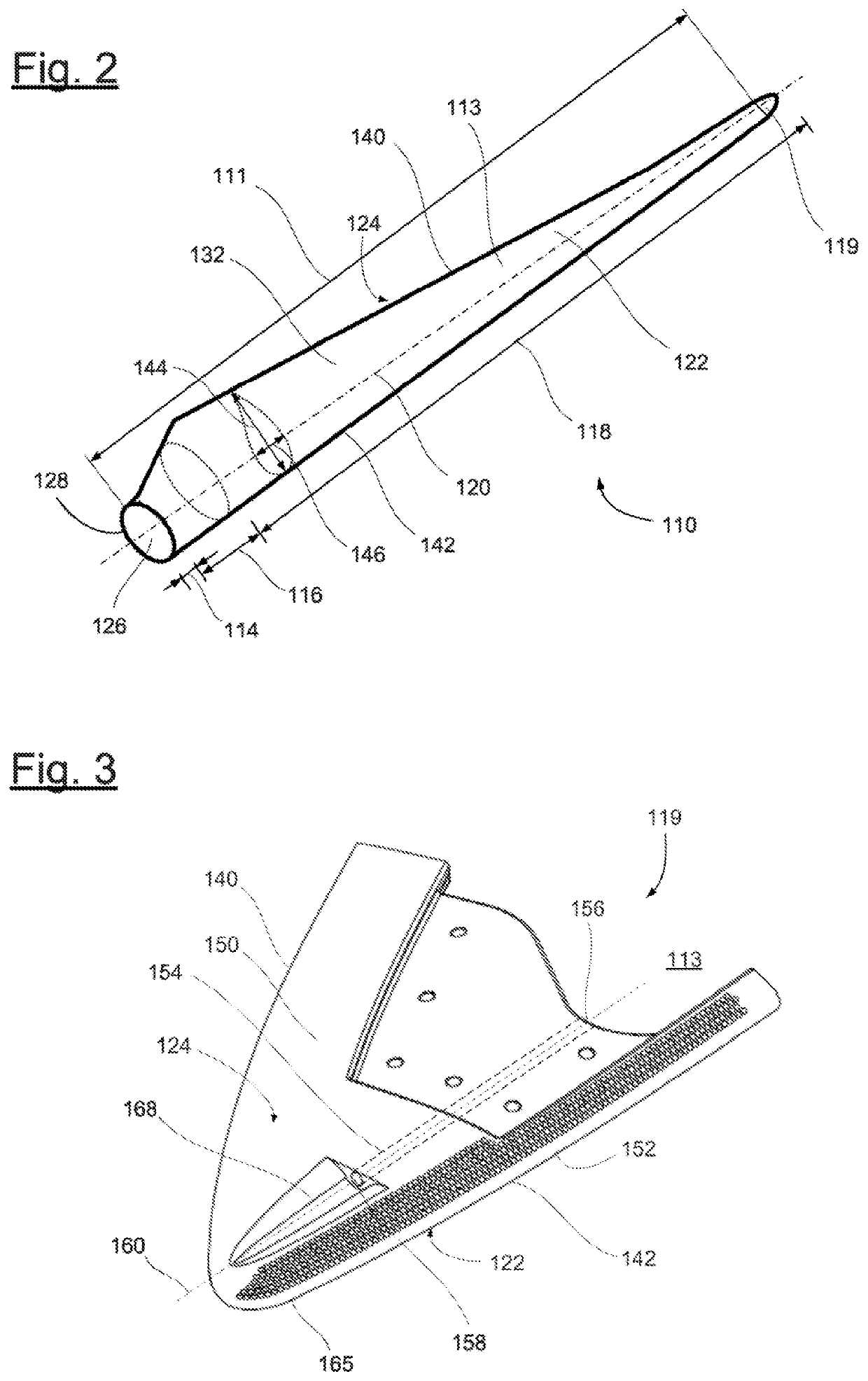
[0028]FIG. 2 schematically shows a rotor blade 110. The rotor blade 110 has the shape of a conventional rotor blade, and is formed by a rotor blade main body 111 and a rotor blade tip 119. The rotor blade tip 119 is configured as a separate element and is manufactured from an aluminum materi...


PUM


Abstract

The invention is directed to a rotor blade for a wind turbine. The rotor blade has a rotor blade main body which delimits a rotor blade cavity. A rotor blade tip is connected fixedly to the rotor blade main body. The rotor blade tip has a drainage bore which is coupled fluidically to the rotor blade cavity and which is open toward a suction side surface of the rotor blade tip, so that, via the drainage bore, fluid from the rotor blade cavity drains to the outside at the suction side surface of the rotor blade tip. The invention is also directed to a rotor blade tip.

Description

CROSS REFERENCE TO RELATED APPLICATION[0001]This application claims priority of European patent application no. 20160359.4, filed Mar. 2, 2020, the entire content of which is incorporated herein by reference.FIELD OF THE INVENTION[0002]The disclosure relates to a rotor blade for a wind turbine, having a rotor blade main body and a rotor blade tip. The disclosure also relates to such a rotor blade tip.BACKGROUND OF THE INVENTION[0003]Current trends in the wind energy industry are leading to longer and longer rotor blades, for example rotor blades with a length of over 80 m. The rotor blades are produced from fiber composite materials and are hollow on the inside. Correspondingly large quantities of air are situated within these cavities. The water bound in the air can condense on the inner side of the rotor blades under corresponding conditions, for example changes in temperature, et cetera, which leads to water accumulations in the rotor blade. This water has to be able to flow out ...

Claims


Application Information

Patent Timeline
IPC IPC(8): F03D1/06F03D80/30
CPCF03D1/0675F03D80/30F05B2260/602F05B2240/302F05B2240/307F05B2240/30Y02E10/72
Inventor OHLERICH, NICKDOOSTTALAB, MEHDIRAUTMANN, CHRISTOF
Owner NORDEX ENERGY SE & CO KG
Why Eureka
Try Eureka