Eureka AIR delivers breakthrough ideas for toughest innovation challenges, trusted by R&D personnel around the world.

Component Connection Verification Device and Method

a technology of component connection and verification device, which is applied in the direction of coupling device connection, transportation and packaging, instruments, etc., can solve the problems of reducing the overall reliability of the system, circuitry not functioning properly, and difficulty in ensuring the correct connection of components, so as to monitor the accuracy of the user or the robotic system affecting the connection

Pending Publication Date: 2021-09-02
APTIV TECH LTD
View PDF4 Cites 2 Cited by
  • Summary
  • Abstract
  • Description
  • Claims
  • Application Information

AI Technical Summary

Benefits of technology

The patent describes a device that can detect and analyze the sound when two parts are connected together using a gripper. The device uses audio sensors placed on the gripper to capture the sounds, and a neural network analyzes the data to identify the connection sound. The device can also provide feedback to the user or a robot about the quality of the connection. The training process involves creating a controlled environment with minimal ambient noise and performing training connections under those conditions. The device has applications in improving the assembly of components and monitoring the quality of the connections.

Problems solved by technology

In some situations, it can be difficult to ensure that components are correctly connected during the manufacture of an assembly.
This is often a particular issue in the case of electronic components, such as the connection of a wire harness and other pin and socket terminals.
Specifically, the failure to correctly mate a connecting pin with its corresponding socket will typically result in the circuitry not functioning properly and / or may decrease its overall reliability.
Furthermore, the fault may not become apparent until after all the components have been assembled.
However, such connection sounds can be difficult to hear, particularly in situations where the connected components are obscured by other parts of the assembly.
For example, this is a common issue in the field of automotive manufacturing, where wire harnesses are often connected by hand around other parts within a partially assembled vehicle.
This situation is exacerbated on a commercial production line because a technician may not be able to hear the connection sound due to background factory noises.
Conventional connector mating assurance systems, such as that disclosed in WO2017 / 0062124, have not however been widely adopted due to a lack of reliability.
In particular, it has proved impractical to filter out background noise from an audible connection signal with any consistency.
However, in real-world scenarios, a technician might grip each connector slightly differently, and there will also be differences between different technicians.
This, in turn, means that this type of filtering offers limited signal improvement.
Furthermore, other digital filtering involving noise subtraction often leads to significant degradation of the overall signal.
Furthermore, whilst filtering may allow a signal encompassing the target connection sound to be extracted, it does not help to classify the connection based on the extracted signal.
As such, conventional connector mating assurance systems have not been effective in commercial applications.
Consequently, a greater number of audio sensors will typically provide an improved resolution of the connection sound, albeit that the number of audio signals that can be simultaneously analysed will be limited by the processing power of the neural network.
Each audio signal sample may then be manually classified to designate it as achieving a desired connection status or resulting in an undesired connection status.

Method used


Image

  • Component Connection Verification Device and Method
  • Component Connection Verification Device and Method

Examples


first embodiment

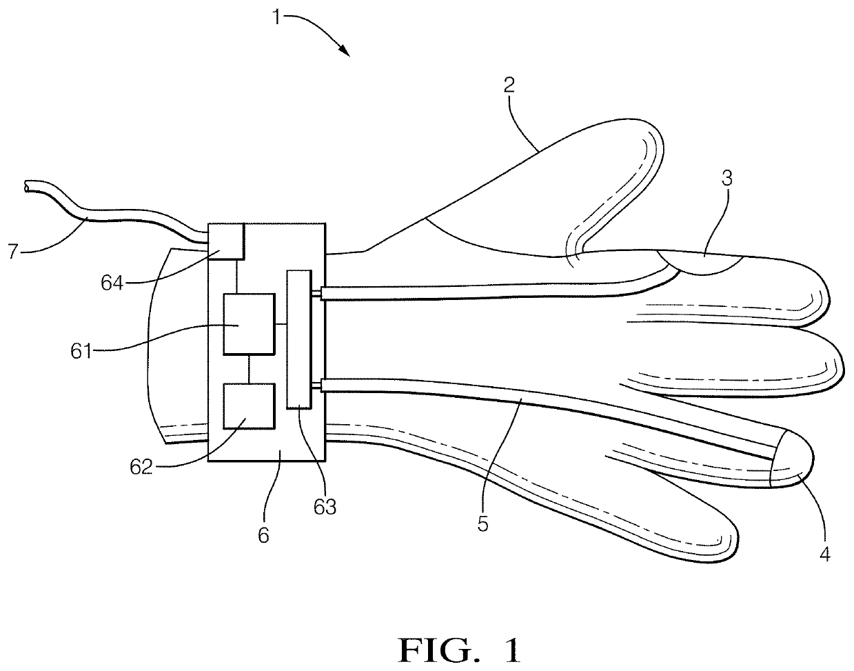
[0029]FIG. 1 shows a connection assurance device 1 according to a This embodiment the device is provided in the form of a wearable glove 2 to be worn by a user, such as a technician or assembly line employee working in an assembly plant.

[0030]The glove 2 is provided with a controller 6 at the cuff of the device, which is connected through connecting wires 5 to a first microphone 3 and a second microphone 4. The first and second microphones 3, 4 are secured to the glove 2 at first and second locations, respectively. These locations are configured such that, when the user's gloved hand grips a component (not shown), the first and second microphones 3, 4 are brought into direct physical contact with the component. When the component is then fitted to its counterpart component, the sound vibrations from the connection are conducted through the component itself, as well as through the air. In other embodiments, other types of audio sensors may also be used, such as vibration sensors. Fu...

second embodiment

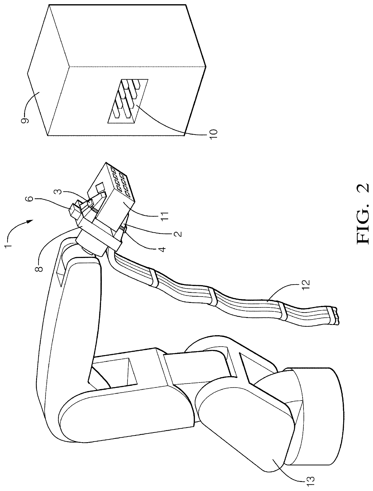
[0038]FIG. 2 shows a connection assurance device 1 according to a In this embodiment, the device 1 is provided in the form of an attachable harness 2 (similar to the glove 2 in FIG. 1) to be fitted to a gripper 8 provided on the distal end of the arm of a production line robot 13.

[0039]The device 1 is provided with first and second microphones 3, 4 that are respectively secured to each finger of the gripper 8 using the attachable harness 2 (e.g., fixture straps). The first and second microphones 3, 4 are connected to the controller 6 by wires 5.

[0040]FIG. 2 further shows the gripper 8 holding the terminal connector 11 of a wire harness for connection into connection port or socket 10 provided in assembly 9. The terminal connector 11 is fed by a bound trunk of cables 12, and the top panel of the connector's housing comprises a latch which engages into a recess formed in the housing of the connection socket 10. The connection socket 10 comprises a plurality of pins which are received...


PUM


Abstract

A device for verifying the connection of components by a gripper, wherein connecting two or more components produces a connection sound. The device comprises a plurality of audio sensors, a fastener for securing the plurality of audio sensors at different positions on the gripper, and a controller. The controller comprises an input for receiving the audio signals from the plurality of audio sensors, a neural network for isolating the connection sound from the audio signals received from the plurality of audio sensors using independent component analysis based on training audio data obtained from audio signals received during a plurality of training connections made in a controlled environment; and an output for indicating a desired connection status based on the isolated connection sound.

Description

CROSS-REFERENCE TO RELATED APPLICATION[0001]This application claims priority to European Patent Application Number 20159891.9, filed Feb. 27, 2020, the disclosure of which is hereby incorporated by reference in its entirety.INTRODUCTION[0002]The present disclosure relates to a device and method for verifying the connection of two or more components. In particular, the present disclosure concerns assuring that connected components are correctly mated. The present disclosure is particularly suited to the field of electronic circuit assembly and the connection of wiring harnesses.BACKGROUND[0003]In some situations, it can be difficult to ensure that components are correctly connected during the manufacture of an assembly. This is often a particular issue in the case of electronic components, such as the connection of a wire harness and other pin and socket terminals. Specifically, the failure to correctly mate a connecting pin with its corresponding socket will typically result in the ...

Claims


Application Information

Patent Timeline
Patent Type & Authority Applications(United States)
IPC IPC(8): G06F3/01G10L25/30G09B5/06G01H1/00G10L21/0208A41D19/00H01R13/64
CPCG06F3/014G10L25/30G09B5/065G10L2021/02087G10L21/0208A41D19/0027H01R13/64G01H1/00H01R43/26H01R13/502G01R31/69H01R13/641B60R16/0207G01N29/14G01N29/226G01N29/4481G01N2291/2697
Inventor SZELEST, MARCINSKRUCH, PAWEL
Owner APTIV TECH LTD
Why Eureka
Eureka Blog
Learn More