
Cooking Device

a technology of cooking device and cooking surface, which is applied in the field of cooking device, can solve the problems of inability to sear the surface, inability to control the temperature of the surface, and unpleasant greasy affair, and achieve the effects of increasing the absorption of infra-red, facilitating a means of temperature control, and increasing the thermal resistan

Pending Publication Date: 2021-09-02
WRIGHT ANDREW CLIVE
View PDF0 Cites 0 Cited by
  • Summary
  • Abstract
  • Description
  • Claims
  • Application Information

AI Technical Summary

Benefits of technology

This patent describes a device that protects food from microwaves to reduce the risk of damage. It uses a metal enclosure to block out the microwazes, allowing more of them to ignite the food. Additionally, the device has a low pressure gas chamber that is enclosed in a thin, resistant film to prevent injury if it were to break. The technical effects of this invention are improved safety and more efficient cooking.

Problems solved by technology

It will be known by anyone who has attempted to cook burgers in a standard (non-grill) microwave oven that the result is a grey, greasy rather unpleasant affair which is not at all palatable.
However, these linear lamps are always placed in the roof of the microwave oven and are thus some distance away from the food to be browned.
Also, some of the output power of the plasma is not in the infrared part of the electromagnetic spectrum that is responsible for heating effects and thus the power of the browning effect is limited.
It is also not possible to sear the surface of meat as might be achieved by the use of a hot frying pan surface and so the creation of cooked hamburgers with a rare-cooked interior and seared exterior is not possible with standard browning lamps in microwave ovens.
Instead, these so-called combination ovens tend to overcook the inside of the meat.
Like all grills, the time for cooking can be rather long and the sales of combination microwave ovens are much lower than that of a standard microwave oven having no grill.
However, these products have to be first pre-heated in the oven and only then after removal from the oven can the food to be cooked be placed on the skillet for a second heating period back in the oven.
This two-step process is somewhat tiresome for the user.
The susceptor layer material can also be rather fragile and so washing can cause damage.
Many of the susceptor skillets also do not reach the temperatures required for proper frying or searing of meat.
Thus no effective cooking device yet exists for frying food in a microwave oven.

Method used


Image

  • Cooking Device
  • Cooking Device
  • Cooking Device

Examples


Embodiment Construction

[0080]Aspects and embodiments of the present invention will now be discussed with reference to the accompanying figures. Further aspects and embodiments will be apparent to those skilled in the art.

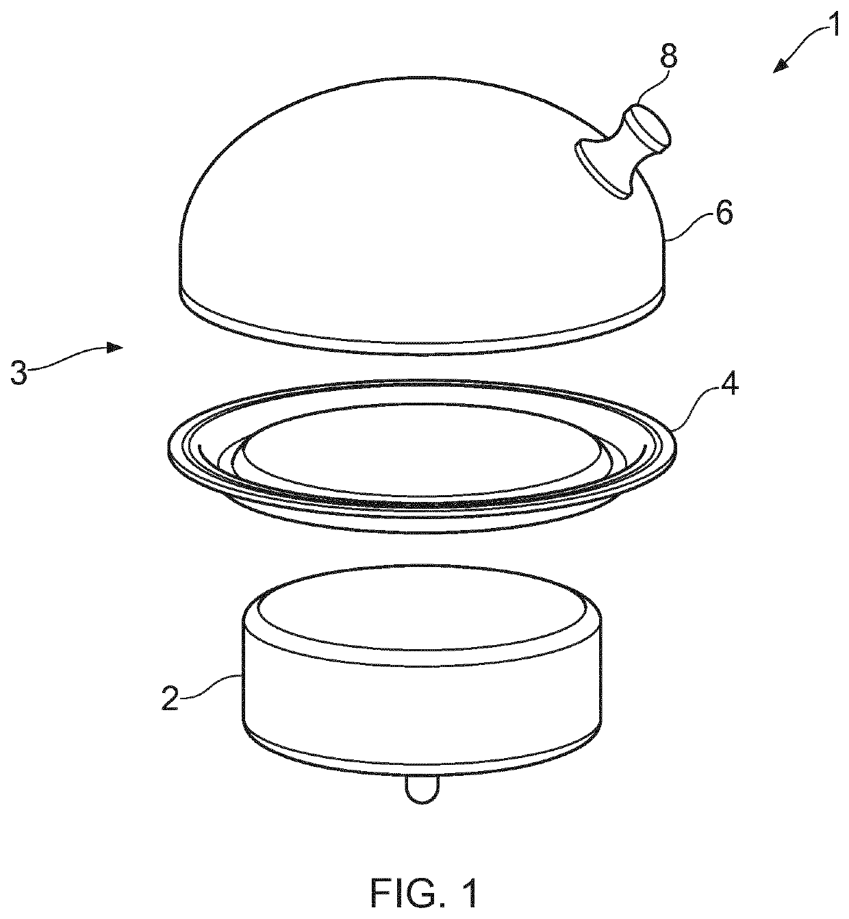
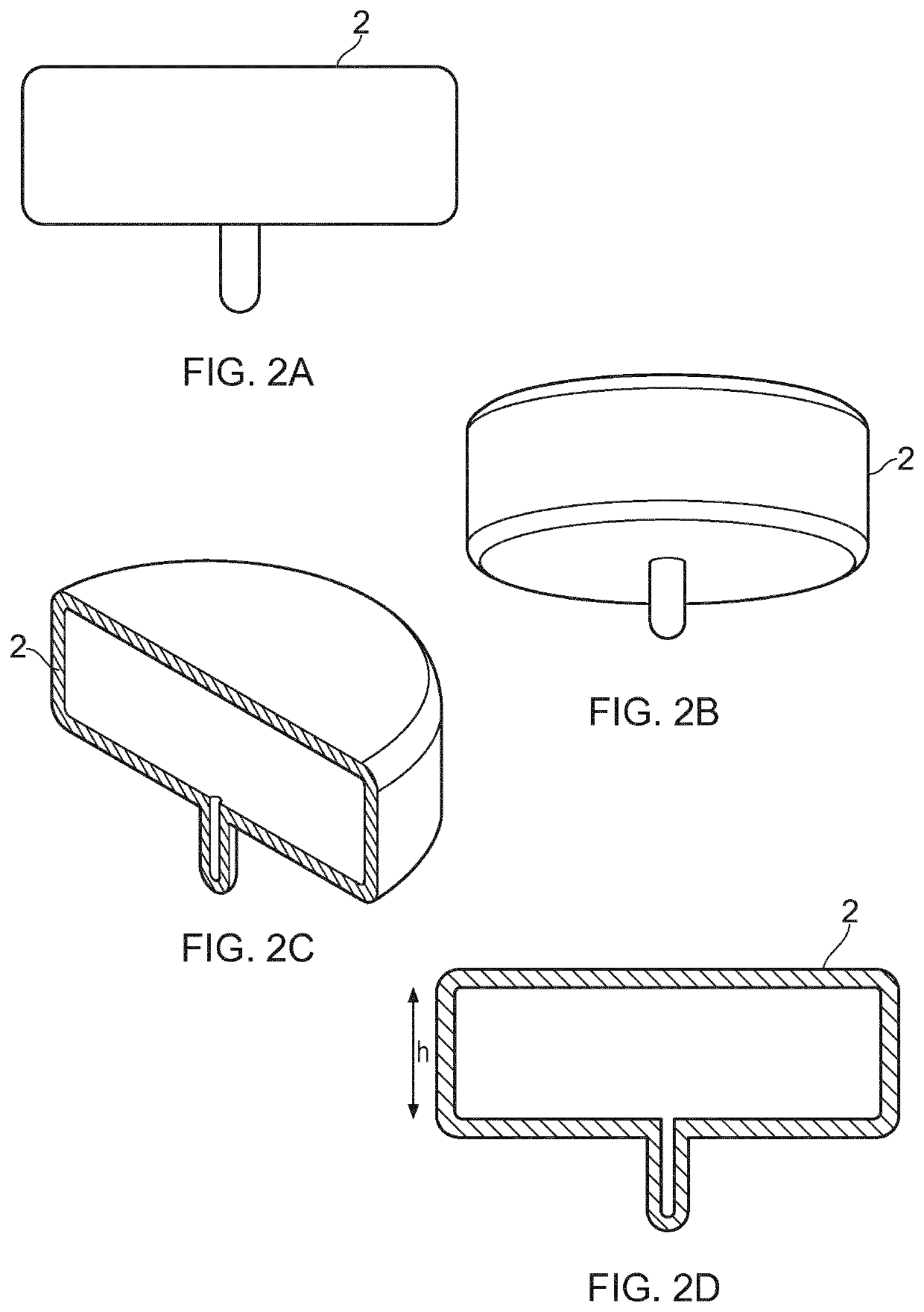
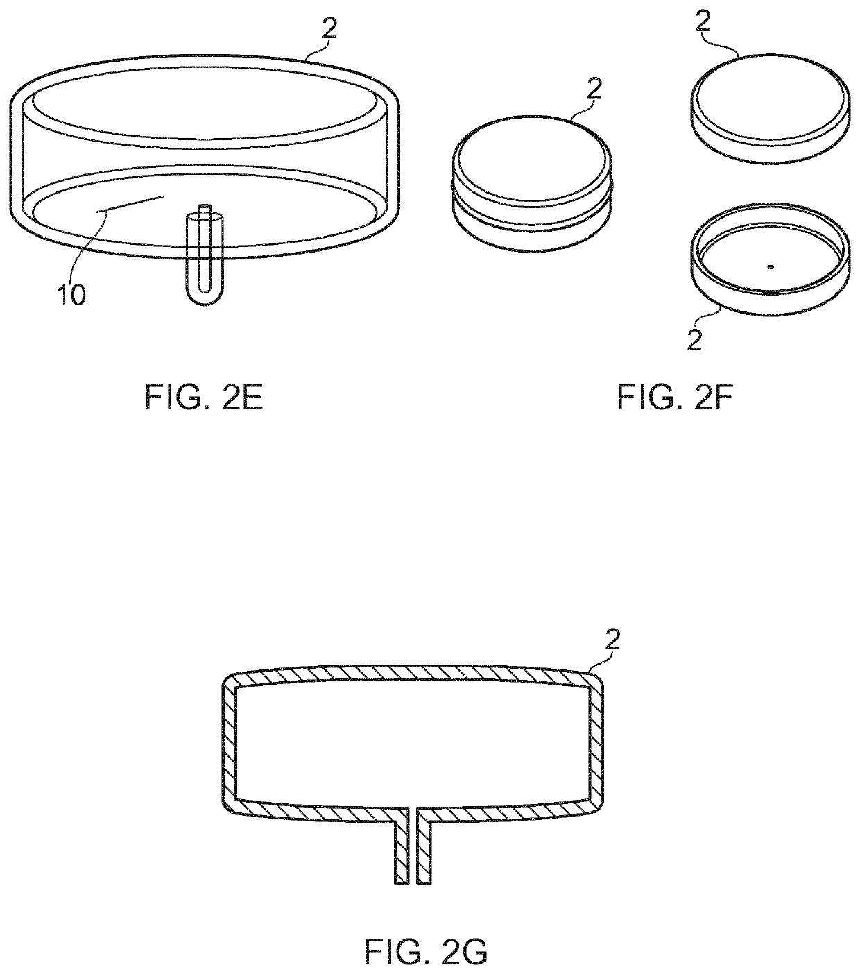
[0081]In the following embodiments is described a way of utilizing the plasma heating effect to create a stand-alone device which can be placed inside a standard simple microwave oven (having no specialised grill or other electrical heating element already installed in the base or roof or walls of the cavity) that provides a frying or cooking effect for food. The central concept is to transfer the heat of gas plasma fluid in a low pressure gas chamber to the walls of the chamber and then by conduction to a metal frying plate 4 in thermal contact with the hot walls of the chamber. For best heat transfer, the outer surface of the chamber and the metal frying plate 4 are conformal to each other and in mechanical contact.

[0082]As shown in FIG. 1, cooking device 1 has a low pressure gas chambe...


PUM


Abstract

A cooking device for frying food in a microwave oven, the cooking device comprising a low pressure gas chamber; a plasma igniting means configured to ignite plasma within the low pressure gas chamber when supplied with microwave radiation; and a cooking enclosure formed of metal, the cooking enclosure defining a food-receiving region and being thermally coupled to the low pressure gas chamber.

Description

FIELD OF THE INVENTION[0001]The present invention relates to a cooking device for frying food in a microwave oven.BACKGROUND[0002]Electromagnetic waves in the microwave region in the spectrum have, following its invention in 1945 by Percy Spencer (U.S. Pat. No. 2,495,429, published 1950), been used commercially to heat food since its introduction in 1954 by the Raytheon® company and the microwave oven is now a common appliance in many domestic kitchens with over 90% of homes in the US owning a microwave oven. Recent developments by the Japanese firm Panasonic® have seen the addition of both a steaming facility and a conventional convection oven mode making the modern microwave a very versatile cooking system. However, microwave energy does not cause selective browning of the outer surface of the food and this has led to the development of microwave oven with an additional grill to facilitate this function. It will be known by anyone who has attempted to cook burgers in a standard (n...

Claims


Application Information

Patent Timeline
Patent Type & Authority Applications(United States)
IPC IPC(8): H05B6/64A47J36/02H05B7/16H05H1/46
CPCH05B6/647A47J36/027H05H1/461H05B7/16H05B6/6408H05H1/46H05B6/806
Inventor WRIGHT, ANDREW CLIVE
Owner WRIGHT ANDREW CLIVE
Learn More