Multiple-stage power conversion

Active Publication Date: 2021-09-16
INFINEON TECH AUSTRIA AG
View PDF3 Cites 4 Cited by
  • Summary
  • Abstract
  • Description
  • Claims
  • Application Information

AI Technical Summary

Benefits of technology

The patent describes a way to improve the power conversion efficiency of conventional power supplies, using a switched-capacitor converter and an efficient generation of an output voltage. The invention involves a second power converter that receives energy from the first output voltage and uses it in each switching control cycle, reducing conduction losses and improving overall efficiency. The switched-capacitor converter includes one or more resonant circuit paths that reduce reactive impedance and further improve efficiency. Overall, this innovation provides a high efficiency for converting input voltage to output voltage.

Problems solved by technology

Additionally, the second power converter provides unregulated conversion of the first output voltage into the second output voltage via the capacitive energy transfer and the magnetic energy transfer.

Method used


Image

  • Multiple-stage power conversion
  • Multiple-stage power conversion
  • Multiple-stage power conversion

Examples


case b

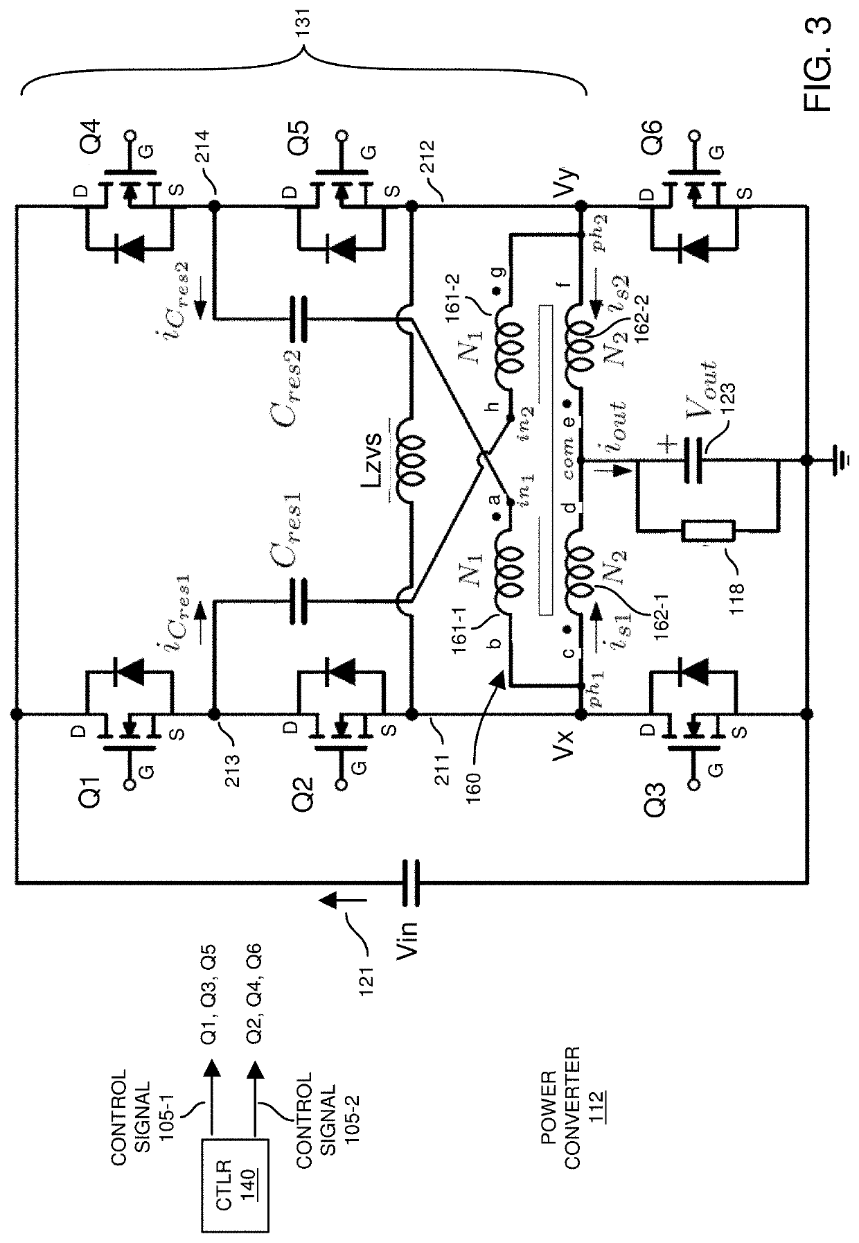
[0326]Magnetizing inductance and the leakage of the multi-tapped autotransformer can be independently controlled during the design or / and manufacture of the multi-tapped autotransformer. By controlling the equivalent area of the core Ae, and also by controlling the equivalent permeability of the core (i.e. having an air gap in the core or using low permeability material), for such applications which require a given N1 turns and N2 turns, embodiments herein enable to modulate the magnetizing inductance of the multi-tapped autotransformer. In FIG. 10, we report a multi-tapped autotransformer construction scheme. Embodiments herein include various options how to connect the nodes of the magnetic device 160, referring to the converter depicted in example FIG. 3, as follows:[0327]Case a: node a is connected to in1, b and c are shorted internally or externally in the multi-tapped autotransformer to reduce the overall copper losses and are then connected to ph1 minimizing the high current ...


PUM


Abstract

An apparatus includes a first power converter and a second power converter. The first power converter converts an input voltage into a first output voltage; the second power converter converts the first output voltage into a second output voltage that powers a load. The second power converter includes a switched-capacitor converter combined with a magnetic device. The switched-capacitor converter provides capacitive energy transfer; the magnetic device provides magnetic energy transfer. Additionally, the second power converter provides unregulated conversion of the first output voltage into the second output voltage via the capacitive energy transfer and the magnetic energy transfer. To maintain the magnitude of the second output voltage within a desired range or setpoint value, the first power converter regulates a magnitude of the first output voltage based on comparison of a magnitude of the second output voltage with respect to a desired setpoint reference voltage.

Description

BACKGROUND[0001]Data centers such as operated by Google™, Facebook™, and others provide indispensable services for our society. The energy consumption for all data centers worldwide is around 2% of overall electric energy usage. Therefore, datacenter providers are constantly looking to improve the efficiency of power conversion in order to save energy or to be able to increase the CPU / GPU / ASIC, etc., power of servers in existing data centers. Machine learning and artificial intelligent architectures require very powerful GPUs or custom designed ASICs to meet the required calculation power.[0002]Higher voltage distribution and efficient conversion systems are necessary to reduce losses and increase the overall power density of the conversion system. In the last few years 48V DC at the rack level has been introduced by vendors enabling several different scenarios to provide high power to digital load, such as CPU / ASIC / GPU. These architectures are coordinated, e.g., by the Open compute...

Claims


Application Information

Patent Timeline
IPC IPC(8): H02M3/07H02M1/08
CPCH02M3/07H02M2001/0058H02M1/083H02M3/00H02M1/007H02M1/0058H02M3/158H02M3/01H02M1/0048Y02B70/10H02M1/0095
Inventor RIZZOLATTI, ROBERTORAINER, CHRISTIAN
Owner INFINEON TECH AUSTRIA AG
Why Eureka
Try Eureka