
Pumped storage water electric power generation facility and reservoir utilizing coal combustion residuals

a technology of coal combustion residuals and electric power generation facilities, which is applied in the direction of mechanical energy handling, mechanical equipment, machines/engines, etc., can solve the problems that the need for long-term energy storage facilities will continue to increase, and achieve the effect of reducing environmental impacts

Active Publication Date: 2021-09-23
HECTOR CARROLL LLC
View PDF0 Cites 0 Cited by
  • Summary
  • Abstract
  • Description
  • Claims
  • Application Information

AI Technical Summary

Benefits of technology

The patent describes a system for storing energy to meet long-term needs and controlling the use of carbon dioxide to reduce environmental impacts. It also includes the ability to remedy existing ponds and landfills that are leaching harmful substances into groundwater. The system has open, recirculating, and closed loop capabilities, with the goal of generating electricity efficiently and reducing emissions.

Problems solved by technology

The need for long duration energy storage facilities will continue to increase because renewable energy, for example, various tide, wind and solar technologies, often do not produce the energy when it is required.

Method used


Image

  • Pumped storage water electric power generation facility and reservoir utilizing coal combustion residuals
  • Pumped storage water electric power generation facility and reservoir utilizing coal combustion residuals
  • Pumped storage water electric power generation facility and reservoir utilizing coal combustion residuals

Examples


Embodiment Construction

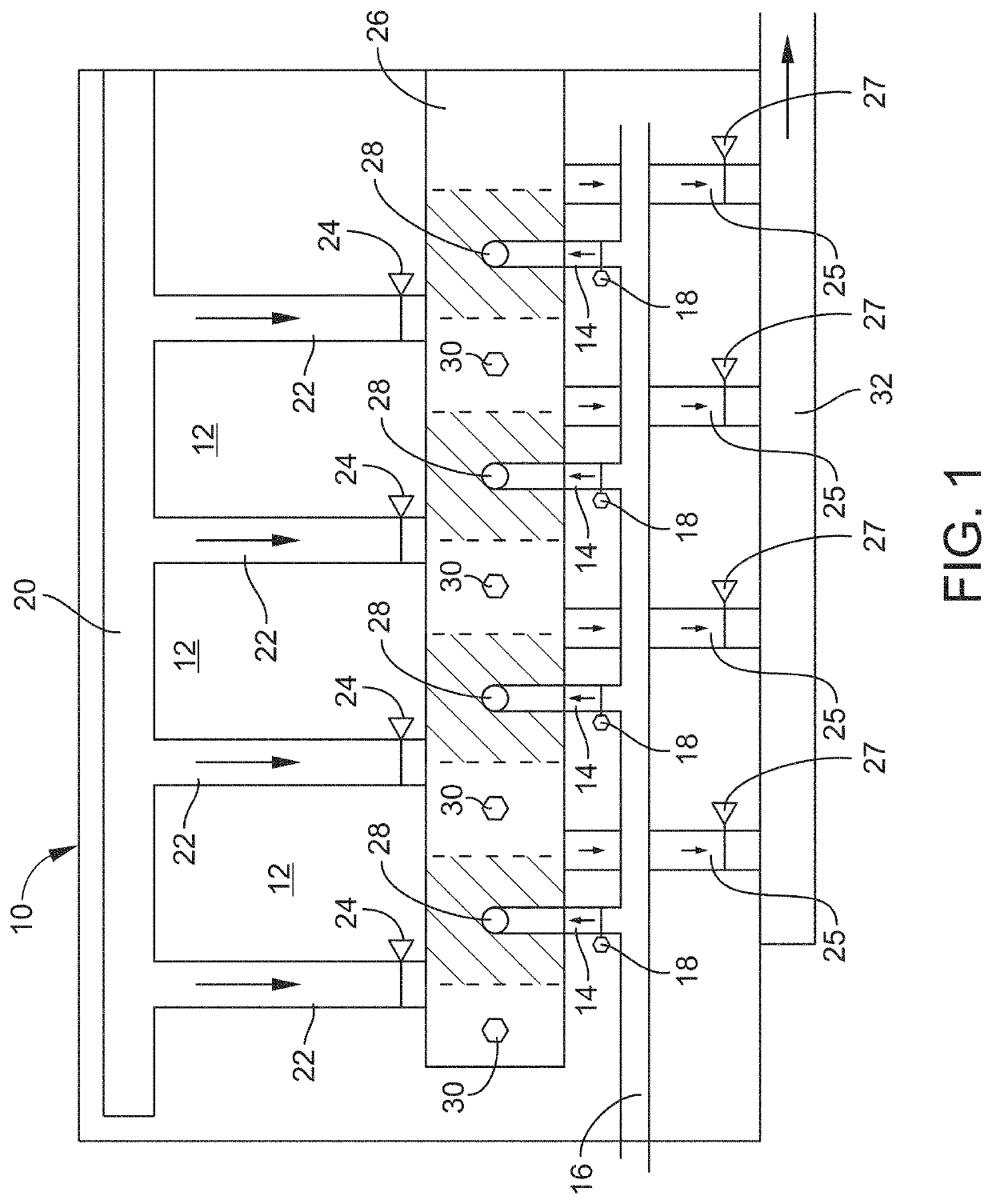
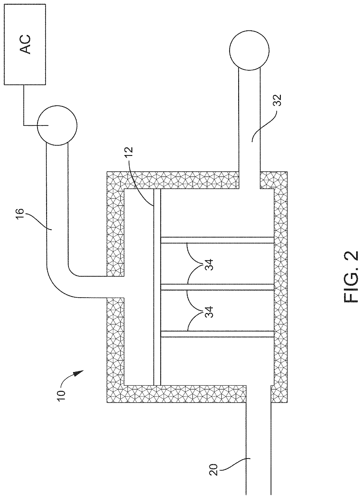
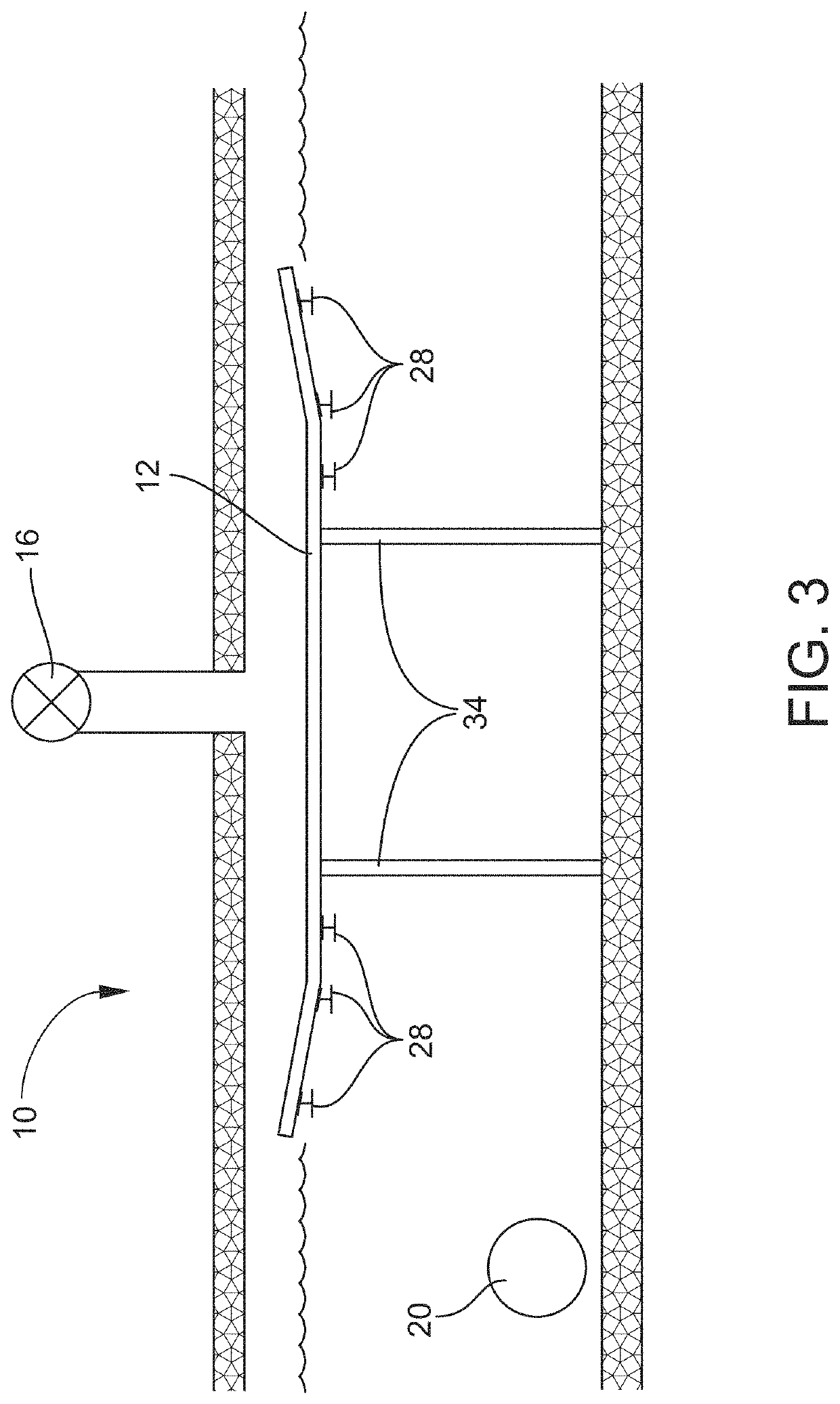
[0045]Referring now to the drawings, FIGS. 1, 2 and 3 illustrate one preferred embodiment of a pumped storage water FIGS. 1 and 2 are top plan, and vertical cross-section views of a pressure vessel 26 used to pressurize water that is then delivered downstream to a hydroelectric turbine. The pressure vessel system 10 includes a pressure vessel 26 that is constructed of suitable pressure-resistant materials, which may include high-strength metals in combination with other non-metallic reinforcing materials. The pressure vessel 26 contains a series of air dispersing plates 12 that receive air pressurized by an air compressor / pressurized air storage tank “AC”, see FIG. 2, through a series of spaced-apart air delivery feed tubes 14 fed by a pressurized air delivery line 16 from the air compressor “AC”. Air flow into the pressure vessel 26 is controlled by air flow valves 18. Water to be pressurized is fed into the pressure vessel 26 through a water feed line 20 that branches into a serie...


PUM


Abstract

A pumped storage electricity generating system that includes a water feed line for introducing water into a pressure vessel. Water flow valves communicate with the pressure vessel to control introduction of water into the pressure vessel. A push plate is mounted for movement in the pressure vessel between opposed first and second winches adapted for reciprocating the push plate linearly between a first direction wherein water is drawn into the pressure vessel through the water flow valves and a second direction wherein water is conveyed downstream through the water discharge line under pressure to the hydroelectric turbine.

Description

PRIORITY CLAIM[0001]This utility patent application is a continuation of U.S. patent application Ser. No. 17 / 316,429, filed May 10, 2021, which is a continuation-in-part of U.S. patent application Ser. No. 17 / 013,070, filed on Sep. 4, 2020, which is a divisional of U.S. patent application Ser. No. 16 / 993,718, filed on Aug. 14, 2020, which is a divisional of U.S. patent application Ser. No. 16 / 713,359, filed on Dec. 13, 2019, which claims priority from Provisional Patent Application Ser. No. 62 / 779,686, filed on Dec. 14, 2018, the contents of which are incorporated by reference in this application.TECHNICAL FIELD AND BACKGROUND OF THE INVENTION[0002]This application relates to the construction and use of pumped storage water reservoirs and, in particular, the construction of such reservoirs utilizing Coal Combustion Residuals (referred to as “CCRs” throughout this application). CCRs, also referred to as “coal ash”, is produced primarily from the burning of coal in coal-fired power pl...

Claims


Application Information

Patent Timeline
Patent Type & Authority Applications(United States)
IPC IPC(8): F03B13/08H02K7/18
CPCF03B13/08H02K7/1823Y02E10/20F03B13/06F05B2270/506F05B2260/422Y02E60/16
Inventor HECTOR, JR., FRANCIS NORBERTCARROLL, JUAN KEITH
Owner HECTOR CARROLL LLC
Learn More