Variable compliance prosthetic socket with breathable matrix

a prosthetic socket and matrix technology, applied in the field of limb prosthesis, can solve the problems of low or no load bearing capacity of conventional prosthetic devices, significantly reduced range of motion, poor heat and moisture management, etc., and achieve the effect of effectively engaging the boney prominences of the limb, easing the transition, and improving the engagement

Active Publication Date: 2021-09-30
STUMPWORX LLC
View PDF6 Cites 0 Cited by
  • Summary
  • Abstract
  • Description
  • Claims
  • Application Information

AI Technical Summary

Benefits of technology

[0014]To exploit the “go” areas, the term “counter” will be used to describe semi-rigid batten-like structures that engage these “go” surfaces for optimal support and control while causing minimal interference. The socket comprises a plurality of these stiff members or counters, each of which connects a plurality of “go areas” without transiting or engaging “no-go” areas. The “go” areas may be better engaged by one or more pads with stiff contoured cores to better engage the boney prominences of the limb. Additional pads may cover other areas of the counters where they contact the limb. One or more lacing systems, parts of which may function as flexible hinges across joints, connect the counters and pads, combining and reinforcing their engaging effects, also without encroaching on no-go areas of the limb. A variable compliance matrix eases the transition between “go” and “no-go” areas, connecting the counters, the lacing system, and the flexible hinges, and provides four-way stretch over the “no-go” areas, allowing the free movement of the soft tissue beneath.
[0015]A socket for engaging a residual limb includes a plurality of hard counters, each configured to engage the residual limb at defined “go points”. The go points can bear pressure without discomfort or impeding range of motion. The counters are further configured to avoid contact with identified “no go” points where excess tissue may inhibit motion or experience irritation upon movement and which include one or more contoured pads to more effectively engage the bony prominences of the limb without inhibiting motion. A chassis from which each of the counters may flexibly depend connects the residual limb mechanically to a limb extension. A lacing system alternately intersects the counters and terminates in a tensioning reel. Rotation of the tensioning reel in a first direction will draw the laces over each of the counters such that the tensioned laces will draw counters together to engage the residual limb.

Problems solved by technology

Relative to the instant invention, conventional prosthetic devices offer low or no-load bearing capacity, suffer from significantly reduced range of motion, poor heat and moisture management, pressure, and poor volume compensation, any of which might cause friction and tissue breakdown on the residual limb.

Method used


Image

  • Variable compliance prosthetic socket with breathable matrix
  • Variable compliance prosthetic socket with breathable matrix
  • Variable compliance prosthetic socket with breathable matrix

Examples


Embodiment Construction

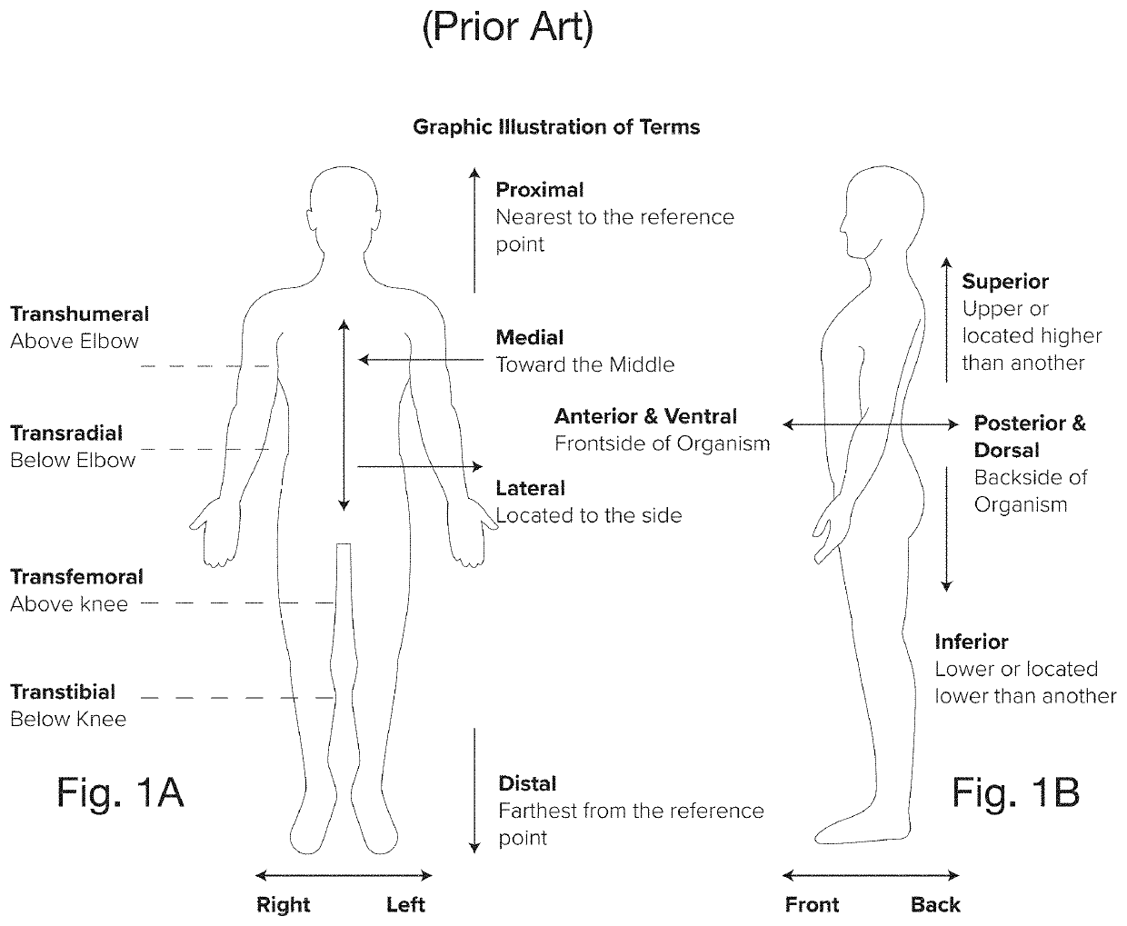
[0040]Throughout this application, certain terms such as “distal” and “medial” have accepted medical meanings. To assist in understanding the teaching of this Specification, the applicant provides FIG. 1, a reference atlas of human body in Standard Anatomical Form (SAF) position with view directions including the terms “medial” and “lateral”; “proximal” and “distal”; and “anterior” and “posterior”. To further aid in discussion of various embodiments of the invention, the names for the locations of different levels of amputation have been identified, including “transradial,”“transhumeral,”“transtibial,” and “transfemoral,” are identified on the same figure.

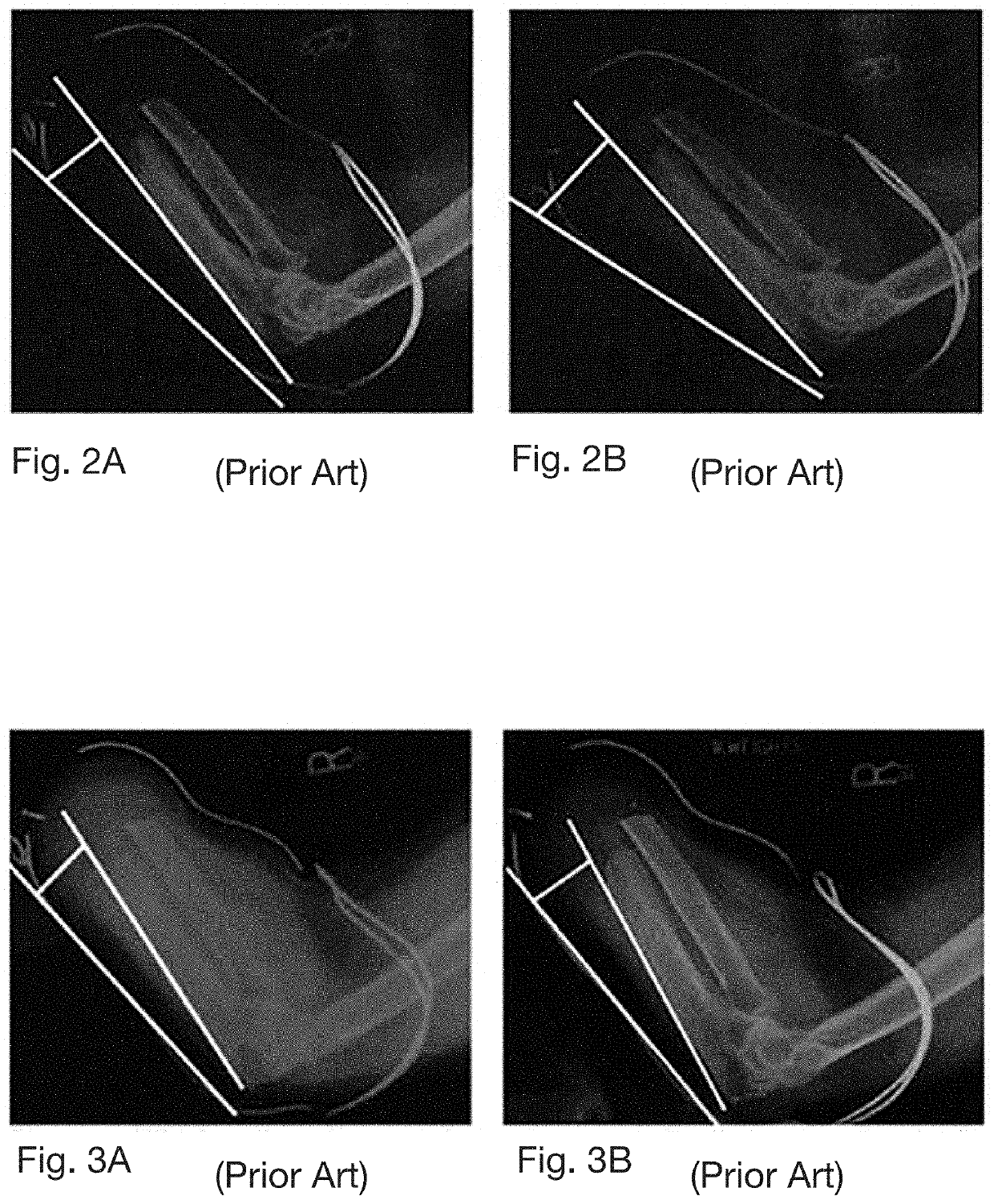
[0041]To express the issues presented by conventional prostheses, the application provides FIGS. 2A and 2B. FIGS. 2A and 2B are a pair of radiographic images depicting a prior art monolithic Meunster Socket both under load and in a no load state, respectively while FIGS. 3A and 3B are a pair of radiographic images of a limb in enga...


PUM


Abstract

A socket for engaging a residual limb includes a plurality of hard counters, each configured to engage the residual limb at defined “go points”. The go points can bear pressure without discomfort or impeding range of motion. The counters are further configured to avoid contact with identified “no go” points where excess tissue may inhibit motion or experience irritation upon movement and which include one or more contoured pads to more effectively engage the bony prominences of the limb without inhibiting motion. A chassis from which each of the counters may flexibly depend connects the residual limb mechanically to a limb extension. A lacing system alternately intersects the counters and terminates in a tensioning reel. Rotation of the tensioning reel in a first direction will draw the laces over each of the counters such that the tensioned laces will draw counters together to engage the residual limb.

Description

REFERENCE TO RELATED APPLICATIONS[0001]This application claims an invention which was disclosed in Provisional Application No. 62 / 911,232, filed on 5 Oct. 2019, entitled “Variable Compliance Joint-Transiting Soft Prosthetic Socket”. The application claims the benefit under 35 U.S.C. § 119(e) of the United States provisional application and the aforementioned application is hereby incorporated herein by reference as if set out here in full.FIELD OF THE INVENTION[0002]The invention pertains to the field of limb prosthesis. More particularly, the invention pertains to structural configuration of such protheses.BACKGROUND OF THE INVENTION[0003]Among the general population, nearly half of all arm amputees either rejects or has never worn a prosthetic arm. Dissatisfaction stems from discomfort resulting from limb contact with the prosthetic suspension or interface (i.e., the point of attachment to the body). Such complaints represent the most frequent reasons for which users reject prosth...

Claims


Application Information

Patent Timeline
Patent Type & Authority Applications(United States)
IPC IPC(8): A61F2/80A61F2/76
CPCA61F2/80A61F2002/503A61F2/76
Inventor KUNIHOLM, JONATHANMEYER, ZACHARY
Owner STUMPWORX LLC
Why Eureka
Try Eureka