Eureka AIR delivers breakthrough ideas for toughest innovation challenges, trusted by R&D personnel around the world.

Module with Gas Flow-Inhibiting Sealing at Module Interface to Mounting Base

a technology of gas flow and sealing, which is applied in the direction of semiconductor devices, semiconductor/solid-state device details, electrical apparatus, etc., can solve the problems of reducing reliability, reducing reliability, and high effort involved in ensuring proper reliability of such a module, so as to reduce reliability, prevent corroding, and improve the reliability

Active Publication Date: 2021-09-30
INFINEON TECH AG
View PDF2 Cites 2 Cited by
  • Summary
  • Abstract
  • Description
  • Claims
  • Application Information

AI Technical Summary

Benefits of technology

The patent describes a module that prevents the corrosion of electronic components by corrosive gases during operation. The module uses a special sealing material at the interface with a mounting base to create a tight connection that prevents the gases from entering the module. This improves the reliability and performance of the module, especially in environments with a lot of corrosive gas.

Problems solved by technology

A high effort may be involved for ensuring proper reliability of such a module.
In long term operation of the module and under harsh conditions (such as the presence of hydrogen sulfide, H2S, and other corrosive gases), it may happen that parts of an electronic component encapsulated or enclosed in an interior of the module are corroded by corrosive media.
This may reduce reliability or may even completely damage the module.
Descriptively speaking, such corrosive gases may create dendrites in corrosive metal pads (made for example of copper and / or silver) of the electronic component which may involve the danger of creating undesired electrically conductive paths and thereby deteriorating the electric reliability.

Method used


Image

  • Module with Gas Flow-Inhibiting Sealing at Module Interface to Mounting Base
  • Module with Gas Flow-Inhibiting Sealing at Module Interface to Mounting Base

Examples


Embodiment Construction

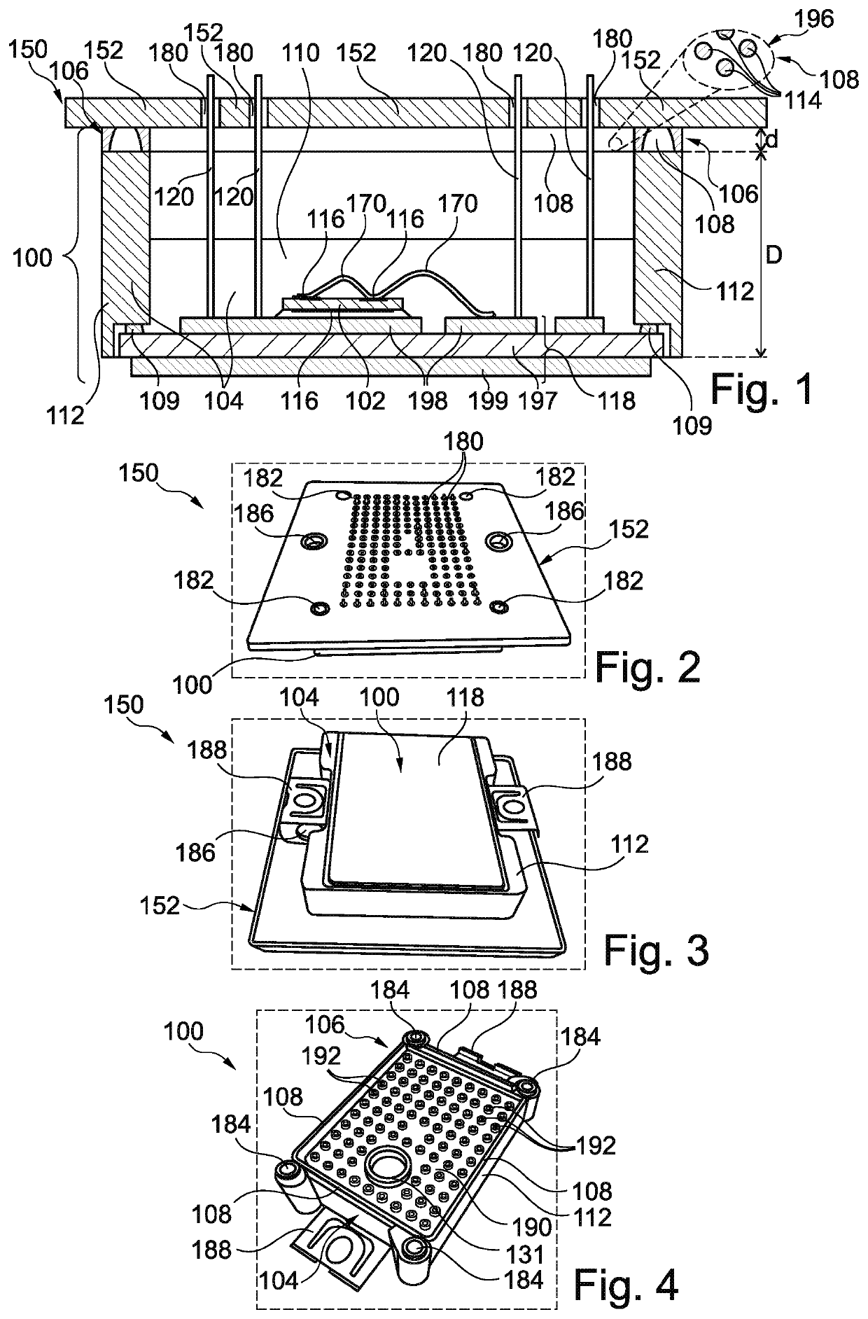
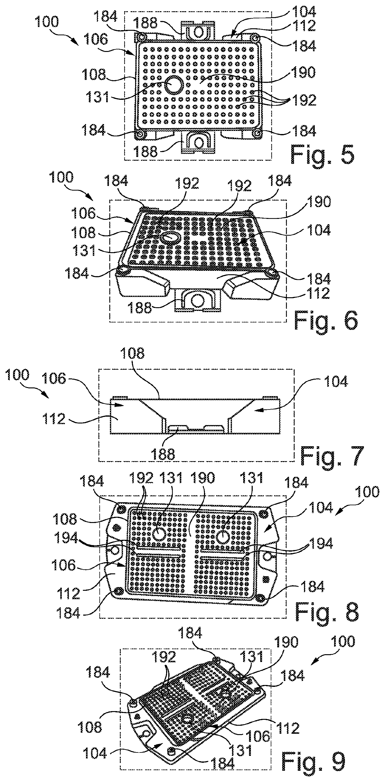
[0012]The illustrations in the drawings are schematic and not to scale.

[0013]Before exemplary embodiments will be described in more detail referring to the figures, some general considerations will be summarized based on which exemplary embodiments have been developed.

[0014]According to an exemplary embodiment, it may be possible to apply a sealing elastomer between a power module and a mounting base (such as a printed circuit board, PCB) for providing a protection against corrosive atmospheric gases.

[0015]Packaging materials in power semiconductor modules may contain metals that are prone to corrosive degradation and humid metal migration effects. These undesired phenomena may be caused by an exposure to water vapor, sulfur containing gases like hydrogen sulfide (H2S), carbonyl sulfide (OCS), gaseous sulfur (S8) and further hazardous gases.

[0016]An elastomeric-type sealing has the advantage that it may establish a reliable connection between the power module and the PCB. Upon mount...


PUM


Abstract

A module includes an electronic component, an enclosure at least partially enclosing the electronic component and defining a module interface at which the module is configured to be mounted on a mounting base, and a gas flow-inhibiting sealing at the module interface and configured to inhibit gas from propagating from an exterior of the module towards the electronic component. An electronic device that includes the module and a method of manufacturing the module are also described.

Description

BACKGROUNDTechnical Field[0001]Various embodiments relate generally to a module, an electronic device, and a method of manufacturing a module.Description of Related Art[0002]A power module provides the physical containment for one or more power components, such as power semiconductor devices. These power semiconductors may be soldered or sintered on a substrate which can be mounted, in turn, on a support body. A high effort may be involved for ensuring proper reliability of such a module.SUMMARY[0003]There may be a need to manufacture a module with high reliability and being usable even under harsh conditions.[0004]According to an exemplary embodiment, a module is provided which comprises an electronic component, an enclosure at least partially enclosing the electronic component and defining a module interface at which the module is to be mounted on a mounting base, and a gas-flow inhibiting (in particular gas-flow tight) sealing at the module interface configured for inhibiting atm...

Claims


Application Information

Patent Timeline
Patent Type & Authority Applications(United States)
IPC IPC(8): H01L23/26H01L23/10
CPCH01L23/26H01L23/10H01L23/04H01L23/3107H01L23/24H01L21/50H01L21/56H01L23/564H01L23/28H01L2224/48227H01L23/053H01L2224/40227H01L24/40H01L24/48H01L2224/45014H01L2224/48132H01L2224/40132H01L2224/05647H01L2224/05639H01L24/06H01L2224/06181H01L24/05H01L2224/0603H01L2224/04026H01L2224/04042H01L2224/04034H01L2224/291H01L2224/8384H01L2224/2919H01L2224/83801H01L24/29H01L24/32H01L2224/32227H01L2224/73265H01L2224/73263H01L24/45H01L25/072H01L23/16H01L25/18H01L25/50H01L2924/00014H01L2224/45099H01L2924/014H01L2924/00012H01L2224/32225H01L2224/73221
Inventor UHLIG, JOHANNESHAGEBUSCH, SVENLUDWIG, MARCONOLTEN, ULRICH
Owner INFINEON TECH AG
Why Eureka
Eureka Blog
Learn More