Air dust removal system and method

Inactive Publication Date: 2021-10-07
SHANGHAI BIXIUFU ENTERPRISE MANAGEMENT CO LTD
View PDF0 Cites 2 Cited by
  • Summary
  • Abstract
  • Description
  • Claims
  • Application Information

AI Technical Summary

Benefits of technology

[0200]189. Example 189 of the present invention provides an air dedusting method including a step of removing

Problems solved by technology

However, the effect of this method is not quite stable, and it also brings

Method used


Image

  • Air dust removal system and method
  • Air dust removal system and method
  • Air dust removal system and method

Examples


embodiment 1

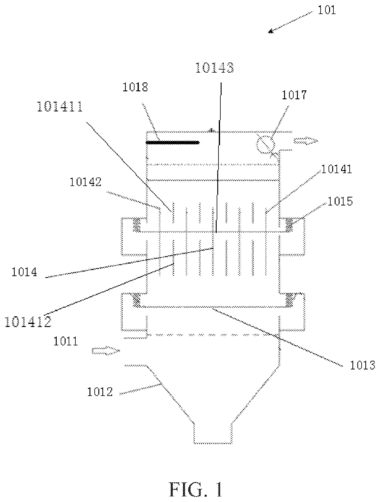
[0378]FIG. 1 shows a structural schematic diagram of an embodiment of an air dedusting system. The air dedusting system 101 includes a dedusting system entrance 1011, a centrifugal separation mechanism 1012, a first water filtering mechanism 1013, an electric field device 1014, an insulation mechanism 1015, an equalizing device, a second water filtering mechanism 1017 and / or an ozone mechanism 1018. In the present invention, the first water filtering mechanism 1013 and / or the second water filtering mechanism 1017 is optional. Namely, the air dedusting system provided in the present invention may include the first water filtering mechanism 1013 and / or the second water filtering mechanism 1017, or it may omit the first water filtering mechanism 1013 and / or the second water filtering mechanism 1017.

[0379]As shown in FIG. 1, the dedusting system entrance 1011 is provided on an intake wall of the centrifugal separation mechanism 1012 so as to receive a gas with particulates.

[0380]The cen...

embodiment 2

[0399]An electric field device shown in FIG. 4 includes a dedusting electric field anode 10141, a dedusting electric field cathode 10142, and an electret element 205. An ionization dedusting electric field is formed when the dedusting electric field anode 10141 and the dedusting electric field cathode 10142 are connected to a power supply. The electret element 205 is provided in the ionization dedusting electric field. The arrow in FIG. 4 shows the flow direction of a substance to be treated. The electret element 205 is provided at an electric field device exit. The ionization dedusting electric field charges the electret element. The electret element has a porous structure, and the material of the electret element is alumina. The dedusting electric field anode has a tubular interior, the electret element has a tubular exterior, and the dedusting electric field element is disposed around the electret element like a sleeve. The electret element is detachably connected with the dedust...

embodiment 3

[0404]An electric field device shown in FIG. 5 and FIG. 6 includes a dedusting electric field anode 10141, a dedusting electric field cathode 10142, and an electret element 205. The dedusting electric field anode 10141 and the dedusting electric field cathode 10142 form a flow channel 292, and the electret element 205 is provided in the flow channel 292. The arrow in FIG. 5 shows the flow direction of a substance to be treated. The flow channel 292 includes a flow channel exit, and the electret element 205 is close to a flow channel exit. The cross section of the electret element 205 in the flow channel occupies 10% of the cross section of the flow channel, as shown in FIG. 7, which is S2 / (S1+S2)□100%, where a first cross sectional area S2 is the cross sectional area of the electret element in the flow channel, the sum of the first cross sectional area S1 and the second cross sectional area S2 is the cross sectional area of the flow channel, and the first cross sectional area S1 doe...


PUM

PropertyMeasurementUnit
Lengthaaaaaaaaaa
Lengthaaaaaaaaaa
Lengthaaaaaaaaaa

Abstract

An air dust removal system (101) and method, comprising a dust removal system inlet, a dust removal system outlet, and an electric field device. The electric field device comprises an electric field device inlet (1011), an electric field device outlet (1012), a dust removal electric field cathode (10142), and a dust removal electric field anode (10141). The dust removal electric field cathode (10142) and the dust removal electric field anode (10141) are used to generate an ionizing dust removal electric field. The present air dust removal system (101) and method may effectively remove particulate matter from the air.

Description

TECHNICAL FIELD[0001]The present invention belongs to the field of air purification, and it relates to an air dedusting system and method.BACKGROUND ART[0002]The layered air covers the earth's surface. Transparent, colorless and tasteless, it is mainly composed of nitrogen and oxygen, which has an important impact on human's survival and production. With the continuous improvement of people's living standard, people have gradually realized the importance of air quality. In the prior art, air dedusting is usually carried out by means of a filter screen. However, the effect of this method is not quite stable, and it also brings about high energy consumption which is easy to cause secondary pollution.SUMMARY[0003]In view of all of the above shortcomings of the prior art, the present invention aims at providing an air dedusting system and method for solving the problems of the prior art of dedusting systems, which are that air dedusting is not implemented efficiently.The present inventi...

Claims


Application Information

Patent Timeline
IPC IPC(8): B03C3/06B03C3/49B03C3/62F24F8/30F24F8/80
CPCB03C3/06B03C3/62B03C3/49B03C3/08B03C3/16B03C3/78B03C3/09B03C3/47B03C3/15B03C3/41B03C3/12B03C3/28B03C3/155B03C3/86B03C3/40B03C3/74B03C2201/12B03C3/68B01D2247/02B01D47/00B01D39/10F01N3/01F24F8/192F24F13/28F02M35/0217F01N13/009Y02A50/20Y02T10/12F24F8/30F24F8/80B03C3/011B03C3/017B03C3/885B03C2201/30F02M35/08B03C3/38B03C2201/22B03C3/70B03C3/88B03C2201/08B03C2201/04B01D53/32B01D53/346B01D53/44B01D2258/06F01N3/05
Inventor TANG, WANFUDUAN, ZHIJUNZOU, YONGANXI, YONG
Owner SHANGHAI BIXIUFU ENTERPRISE MANAGEMENT CO LTD
Why Eureka
Try Eureka