Modular electrolyzer unit to generate gaseous hydrogen at high pressure and with high purity

a gaseous hydrogen, high-purity technology, applied in the direction of electrolysis components, electrolysis processes, cells, etc., can solve the problems of cumbersome solutions, no purity level, no pressure of gaseous hydrogen produced, etc., to prevent cell deformation, stable cell resistance, and avoid the effect of reducing the contact area

Active Publication Date: 2021-10-07
THALESNANO ZRT
View PDF4 Cites 1 Cited by
  • Summary
  • Abstract
  • Description
  • Claims
  • Application Information

AI Technical Summary

Benefits of technology

[0016]In particular, the invention relates to new components and a new assembly of a water electrolyzer unit capable of operating at high differential pressures. It is based on the electrochemical reduction (2H3O++2e−=H2+2H2O) and oxidation (H2O−2e−=2H++0.5O2) of water (H2O) on the cathode and anode sides, respectively. Due to the proposed technological novelties as well as the modular construction, the presented electrochemical unit architecture is highly scalable and flexible. The unit can be easily scaled up, both in terms of its size / dimensions and the number of cells made use of, while maintaining pressure tolerance. The catalytic recombiners integrated into each electrolyzer cell allow high gas purity over a wide range of pressures and H2 flow-rates. This allows the application of the inventive electrolyzer unit in various industries, such as the chemical, pharmaceutical, and energy industry. High pressure and high purity are especially important in synthetic organic chemistry (both in pharmaceutical and chemical industries) and in the field of energy storage, especially in the automobile sector.
[0017]One of the new components made use of in the water electrolyzer unit according to the invention is a modular bipolar plate. Instead of the conventional single-item bipolar plates, two-component bipolar plate assemblies are employed in the unit, said assemblies being built up of two separate plate components fabricated also separately. Between the two components, circular cavities are introduced that were found to be effective gas transportation avenues to the channels connecting the adjacent cells of the stack. The two-component design results in thinner bipolar plates when assembled, and an overall lighter electrolyzer unit. In addition, if needed because of any reasons, the half of said bipolar plate assembly, i.e. one of its two components can be changed independently of the other component, further increasing thereby the flexibility of each cell of the stack of the unit.
[0018]A further new component employed in the water electrolyzer unit according to the invention is a H2 / O2 recombiner that is integrated into the cavities formed within the separate components of the two-component bipolar plate assembly. The H2 / O2 recombiner, provided in the form of a large surface mesh, helps to increase the purity of the gaseous streams (H2, O2) generated within the electrolyzer unit according to the invention by means of enhancing the catalytic recombination reaction between either gas and the minor traces of the other gas being present therein.
[0019]A yet further new component made use of in the water electrolyzer unit according to the invention is a custom designed and assembled current collector made of titan (Ti) frits (Ti-frits). Said Ti-flits are made of a catalyst-coated Ti powder provided in the form of individually coated Ti-particles of different average particle size, wherein a nanoparticulate catalyst is deposited by wet chemical processes on the surface of each Ti-particle before the Ti-flits are actually manufactured by pressing the catalyst-impregnated Ti-particles. In this way, the effective surface area of the active catalyst is significantly increased which results in the enhancement of the purity of the gaseous hydrogen generated in the electrolyzer unit according to the present invention.
[0021]A yet further new component optionally employed within the water electrolyzer unit according to the invention is a pressure chamber at both end of the unit formed within specific pressure chamber plates arranged at both ends of the unit. These special plates provide adaptive pressure control on the stack of cells from both sides, thus providing uniform pressure distribution throughout each cell of the stack. This construction inhibits deformation of the cell body, and thus avoids the decrease in the contact area between the internal components, such as e.g. the catalyst-coated membrane and the Ti-frit and / or the Ti-frit and a Ti-plate. This results in a stable cell resistance even at elevated pressures. Importantly, the application of said pressure chamber plates eliminates the requisite of any moving parts (such as pistons or valves) or elastic plastic elements as pressure controlling means within the unit, which is the current state-of-the-art. Furthermore, unlike any external pressure control, the employment of said pressure chamber plates is inherently safe, because the pressure in the pressure chambers formed in said pressure chamber plates can never be higher than that generated in the electrolyzing cells of the stack. It is found, however, that to ensure the pressure independent electrochemical performance, the pressure chambers have to be used in pairs, i.e. one at the cathode-side and another at the anode-side of the electrolyzer unit according to the invention.

Problems solved by technology

Although, a gaseous hydrogen of relatively high pressure (up to about 340 bar) can be produced with the apparatus, the level of purity of the obtained gas is not available.
Neither the pressure of the gaseous hydrogen produced, nor the level of purity is available.
In literature, it is a known issue to produce gaseous hydrogen at high pressure via electrolysis.
These solutions are cumbersome, and in some cases are not reliable enough to operate in an autonomous manner without human monitoring and intervention.
It is a known further issue to produce gaseous hydrogen with high purity.
None of these solutions proves, however, satisfactory.
In particular, a recombiner within the membrane will gradually destroy the membrane and thus shortens its lifetime.
Application in the form of a backing on the titan-fit becomes insufficient at higher pressures.
Making use of external recombiners significantly raises the costs of the H2 generation, requires extra place which is not available within the instrument and may even be dangerous due to the fact that the hydrogen gas has to travel from the cell to the recombiner through the instrument.

Method used


Image

  • Modular electrolyzer unit to generate gaseous hydrogen at high pressure and with high purity
  • Modular electrolyzer unit to generate gaseous hydrogen at high pressure and with high purity
  • Modular electrolyzer unit to generate gaseous hydrogen at high pressure and with high purity

Examples


Embodiment Construction

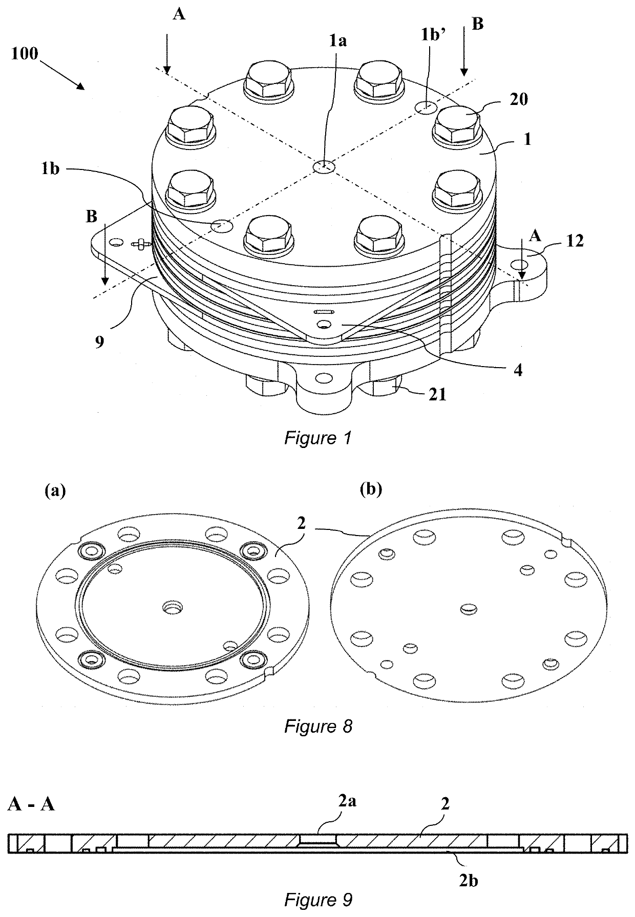
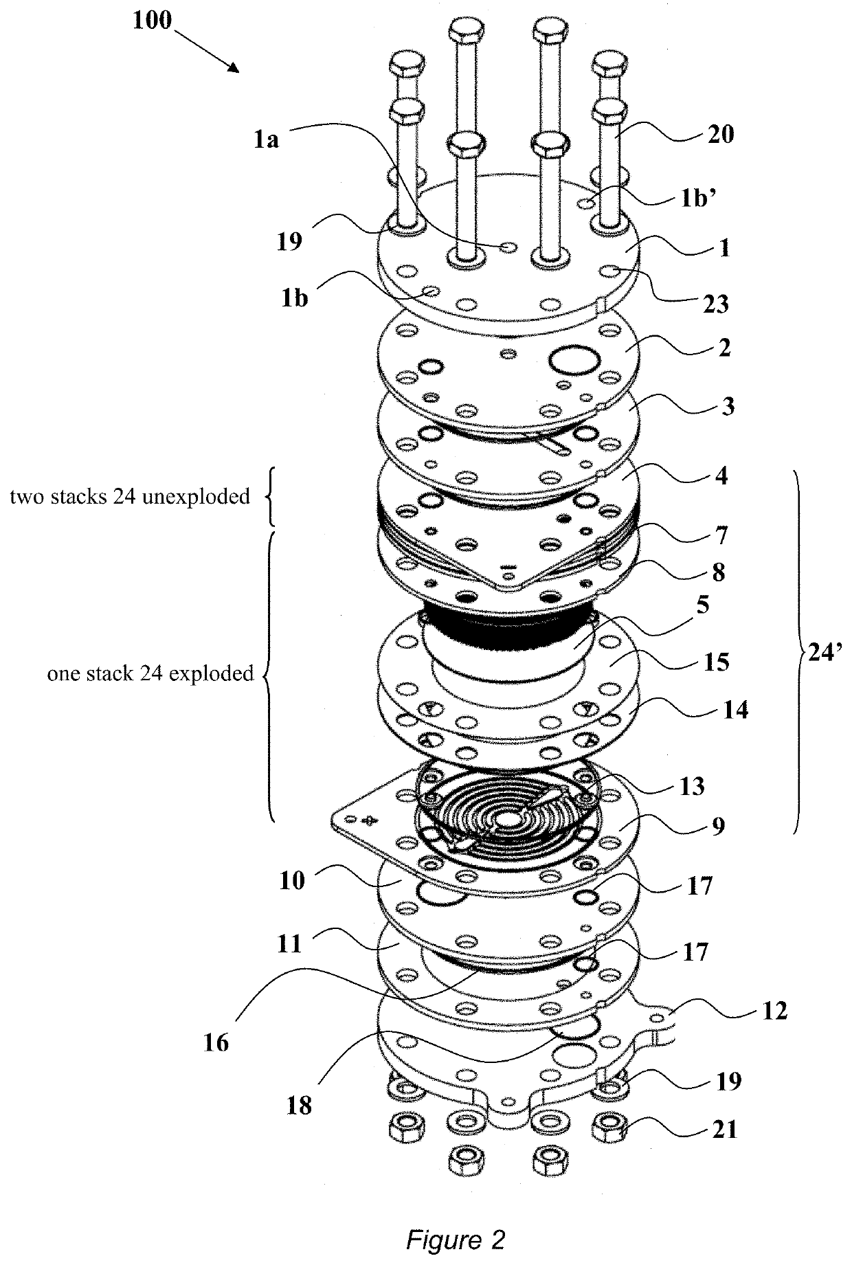
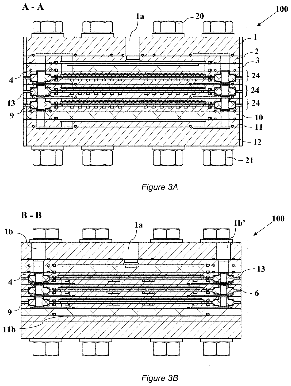
[0040]FIGS. 1 to 3 illustrate an exemplary embodiment of an electrolyzer (electrochemical) unit 100 according the invention used to generate gaseous hydrogen at high pressures and with high purities via the electrolysis of water introduced into said unit 100. In particular, FIG. 1 is the perspective view of the unit 100, while FIG. 2 and FIGS. 3A and 3B are a partial exploded view, a cross-sectional elevation taken along the A-A line and another cross-sectional elevation taken along the B-B line of said electrolyzer unit 100, respectively, shown in FIG. 1. For further reference, the cross-sectional elevation of FIG. 3A reveals the H2 transport channel structure within the unit 100, while the cross-sectional elevation of FIG. 3B shows the water / O2 transport channel structure. Furthermore, in FIGS. 1 to 3, for the sake of simplicity and clarity, an embodiment of the electrolyzer unit 100 comprising three electrolyzing cells 24 arranged adjacent to (on top of) one another and in fluid / ...


PUM

PropertyMeasurementUnit
pressureaaaaaaaaaa
pressuresaaaaaaaaaa
pressuresaaaaaaaaaa

Abstract

The present invention relates to the field of generating gaseous hydrogen at high pressures and with high purity via electrolysis of water by means of an electrolyzer unit (100) with a novel structure.

Description

FIELD OF THE INVENTION[0001]The present invention relates to the field of generating gaseous hydrogen at high pressures and with high purity via electrolysis of water. The invention also relates, thus, to a novel modular electrolyzer unit to perform said electrolysis, as well as a hydrogen generator that employs the electrolyzer unit.BACKGROUND ART[0002]New hydrogen generation technologies are being driven by the move towards the use of hydrogen as an energy carrier. Water elecrolysis by means of polymer-electrolyte membranes (PEM) arranged between cathode and anode plates is a promising hydrogen generation technique, a comprehensive review on PEM water electrolysis is provided in the International Journal of Hydrogen Energy 38 (2013) pp. 4901-4934.[0003]U. S. Published Patent Appl. No. 2011 / 0266142 A1 discloses a unitized electrolyzer apparatus for generating hydrogen gas at high pressures. According to one embodiment, the apparatus includes a pressure-containment vessel, a water e...

Claims


Application Information

Patent Timeline
Patent Type & Authority Applications(United States)
IPC IPC(8): C25B9/05C25B1/04C25B9/19C25B9/17
CPCC25B9/05C25B9/19C25B1/04Y02E60/36C25B9/77C25B9/75C25B9/15C25B15/083
Inventor JANÁKY, CSABAKECSENOVITY, EGONDANYI, ANTALENDRŐDI, BALÁZSTÖRÖK, VIKTORDARVAS, FERENCJONES, RICHARD
Owner THALESNANO ZRT
Why Eureka
Try Eureka