
Methods of placing large bore aspiration catheters

Pending Publication Date: 2021-10-14
IMPERATIVE CARE INC
View PDF0 Cites 16 Cited by
  • Summary
  • Abstract
  • Description
  • Claims
  • Application Information

AI Technical Summary

Benefits of technology

The present invention relates to devices for removing blood clots from blood vessels and includes a system that uses a catheter and a hemostasis valve to prevent blood leakage during the procedure. Additionally, the invention provides an aspiration system with accelerated response that includes a valve to minimize fluid loss during the procedure. The technical effects of the invention are improved blood clot removal with reduced bleeding and improved patient outcomes.

Problems solved by technology

Thrombotic restrictions and occlusions within a patient's blood vessels are a significant medical problem and often require intervention to remove these restrictions and blockages to restore health to patients.
These approaches result in multiple catheterization lab visits, lengthy hospital stays and often lead to bleeding complications.
Acute PAO is usually due to thrombosis of the peripheral vasculature and is associated with a significant risk of limb loss.
Clot aspiration using certain commercial vacuum-assisted thrombectomy systems may sometimes need to be terminated due to the risk of excessive blood loss by the patient, especially when using large aspiration catheters.
Under such conditions, the total volume of blood loss is excessive, and in some cases, may result in premature termination of the procedure.
The aggregate blood loss may reach an unacceptable level before sufficient clot is removed.

Method used


Image

  • Methods of placing large bore aspiration catheters
  • Methods of placing large bore aspiration catheters
  • Methods of placing large bore aspiration catheters

Examples


example embodiments

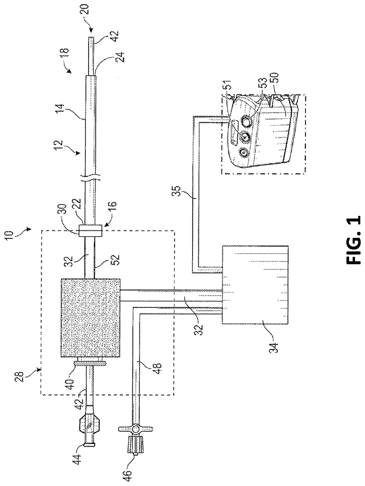
[0205]An aspiration system with accelerated response, comprising one or more of the following:

[0206]an aspiration pump in communication with a first chamber;

[0207]an aspiration catheter configured for placement into fluid communication with the first chamber by way of an aspiration tube;

[0208]a second chamber in between the aspiration tube and the catheter; and

[0209]a valve between the second chamber and the aspiration catheter;

[0210]wherein upon opening of the valve with negative pressure in the first and second chambers, resistance to fluid flow between the second chamber and the distal end of the catheter is less than the resistance to fluid flow between the second chamber and the first chamber, causing a rapid aspiration into the second chamber.

[0211]An aspiration system as described in any embodiment herein, further comprising a handle on the aspiration catheter, and the second chamber is carried by the handle.

[0212]An aspiration system as described in any embodiment herein, fu...


PUM


Abstract

A methods of placing large bore aspiration catheters is disclosed. The method of removing a vascular obstruction includes the steps of transvascularly advancing a distal end of an aspiration catheter into proximity with an obstruction, activating a low flow, detection mode of aspiration through the catheter, and thereafter activating a momentary control to activate a high flow, aspiration mode of operation and draw obstructive material into the distal end of the access catheter.

Description

CROSS-REFERENCE TO RELATED APPLICATIONS[0001]This application claims the priority benefit under 35 U.S.C. § 119(e) of U.S. Provisional Patent Application No. 63 / 044,511, filed Jun. 26, 2020, the entirety of which is hereby incorporated by reference herein. This application is a continuation-in-part of U.S. patent application Ser. No. 17 / 125,723, filed Dec. 17, 2020, which claims the priority benefit under 35 U.S.C. § 119(e) of U.S. Provisional Patent Application No. 62 / 950,058, filed Dec. 18, 2019 and U.S. Provisional Patent Application No. 63 / 064,273, filed Aug. 11, 2020, the entireties of which are hereby incorporated by reference herein.BACKGROUND OF THE INVENTION[0002]Thrombotic restrictions and occlusions within a patient's blood vessels are a significant medical problem and often require intervention to remove these restrictions and blockages to restore health to patients. While applicable to a wide range of vascular applications in both the arterial and venous systems, includ...

Claims


Application Information

Patent Timeline
IPC IPC(8): A61B17/22A61M1/00A61M39/06A61M29/00
CPCA61B17/22A61M1/74A61M39/06A61M2039/062A61B2017/22079A61M2205/3334A61M29/00A61M39/0613A61B17/22031A61B2017/00685A61B2017/22034A61B2017/22038A61B2017/22082A61B2090/065A61B2090/373A61B2090/3784A61B2217/005A61B2217/007A61B2017/320775A61B17/221A61M39/0606A61M2039/0673A61M2039/068A61M1/71A61M1/79A61M39/10A61M2205/7545A61B5/0084A61B5/0215A61B5/6852A61B8/12A61B8/445A61B2017/00323A61B2017/00907A61B2090/034A61B2090/0807A61B2218/007A61B2505/05A61M39/223A61M39/24A61M39/28A61M2039/229A61M2039/244A61B2017/22045A61B2017/00367A61M25/0028A61M25/0136A61M25/02A61M25/09A61M2025/024A61M2025/0293A61M2025/09116A61M1/84A61B2017/00778
Inventor BUCK, MICHAELFOX, JULIAJACOBS, JAMES
Owner IMPERATIVE CARE INC
Learn More