Dynamic mixer dispense valvefor two-component high-viscosity high ratio compounds having quick change cartridge

a technology of high-viscosity, high-ratio compounds and valves, which is applied in the direction of mixing, transportation and packaging, rotary stirring mixers, etc., can solve the problems of not being able to flush solvents, polysulfide has poor miscibility with solvents, and cannot be disposable, so as to achieve high ratio, high viscosity, and high dispersion

Pending Publication Date: 2021-10-21
MENK BRUCE H +1
View PDF0 Cites 1 Cited by
  • Summary
  • Abstract
  • Description
  • Claims
  • Application Information

AI Technical Summary

Benefits of technology

[0013]Accordingly, it is a general object of the present invention to provide an improved and more effective dynamic mixer dispense valve and dispensing apparatus suitable for use in mixing and applying high viscosity, disparate viscosity, high ratio, and / or relatively immiscible two part compounds that sometimes exhibit short cure times. It is a more particular object of the present invention to provide such an improved and effective dynamic mixer dispense valve and metering apparatus which facilitates use in a robotic environment and is suitable for flexibility of application duration so as to facilitate both short shot and long path deposition of such two component sealant and adhesive compounds while avoiding problems of unreliable interruption or termination of compound flow between shot cycles, for example, oozing dripping.

Problems solved by technology

They typically do a better job of mixing compared to a static mixer especially with more difficult to blend liquid compounds.
Most dynamic mixers are not disposable and require cleaning for reuse such as solvent flushing.
Polysulfide has poor miscibility with solvents so in this ease solvent flushing is not an option.
Manual cleaning is not viable in production environment.

Method used


Image

  • Dynamic mixer dispense valvefor two-component high-viscosity high ratio compounds having quick change cartridge
  • Dynamic mixer dispense valvefor two-component high-viscosity high ratio compounds having quick change cartridge
  • Dynamic mixer dispense valvefor two-component high-viscosity high ratio compounds having quick change cartridge

Examples


Embodiment Construction

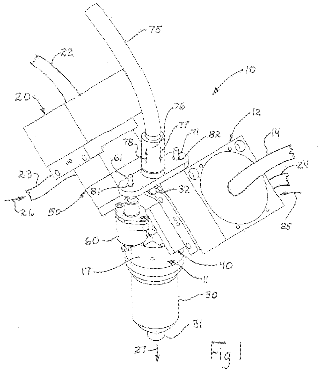
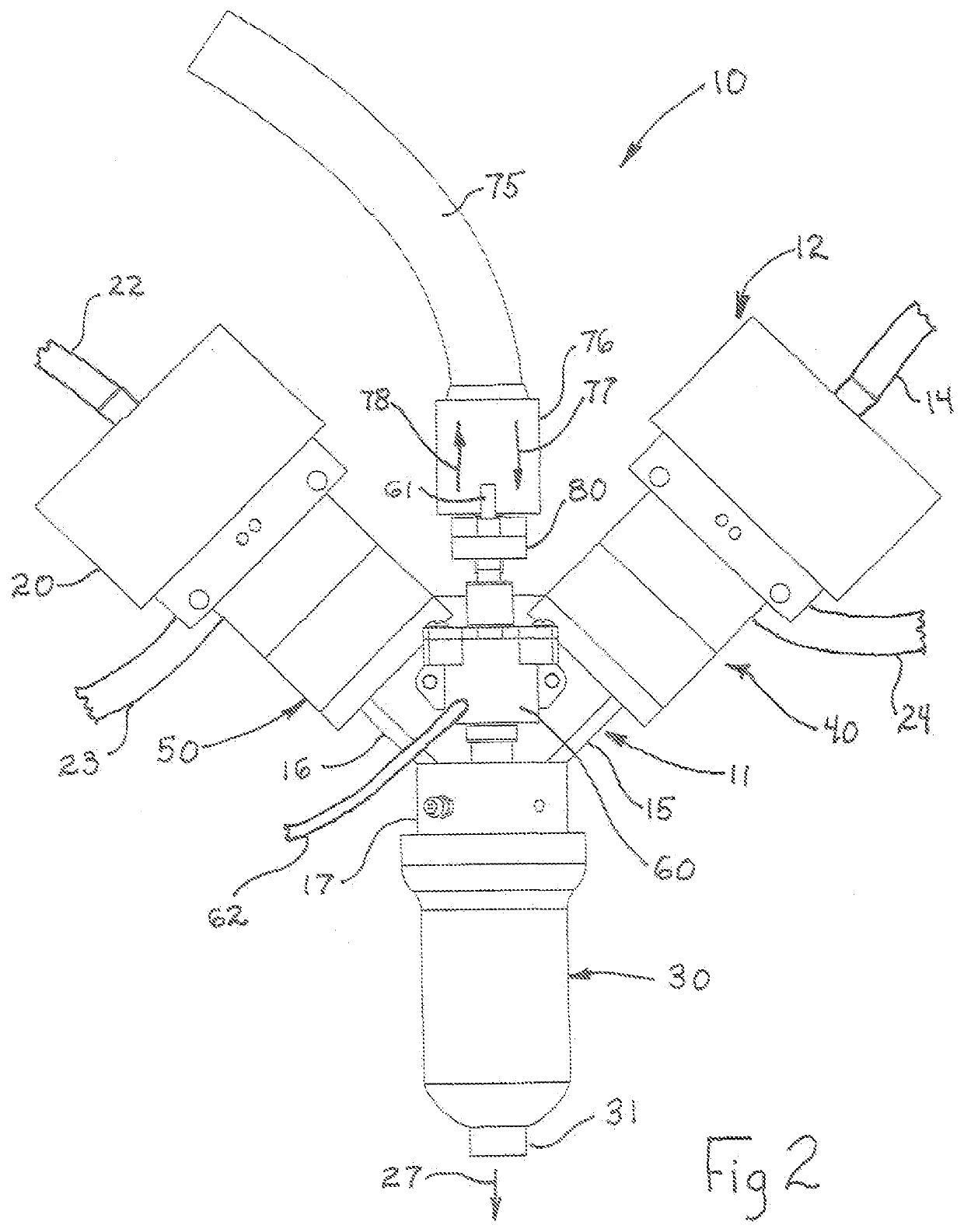
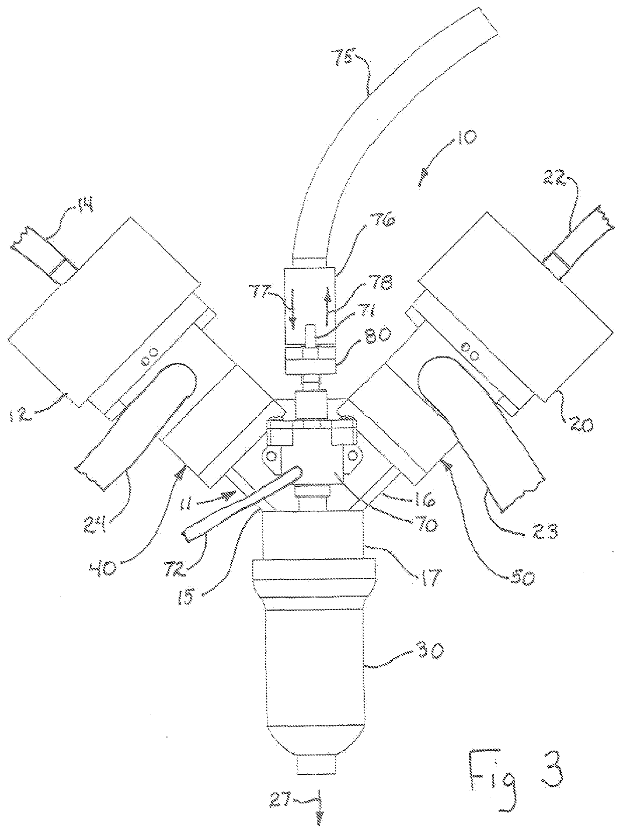
[0037]FIG. 1 sets forth a perspective view of a dynamic mixer dispense valve for two-component, high viscosity, high-ratio, disparate viscosity compounds constructed in accordance with the present invention and generally referenced by numeral 10. Dynamic mixer dispense valve 10 includes a valve manifold 11 which, as is better seen in FIG. 2, defines a generally “Y-shaped” housing having diverging upper valve manifold portions 15 and 16 supporting valve housings 40 and 50, respectively, extending outwardly at diverging angles from valve manifold 11 and a downwardly extending cartridge manifold 17 which in turn supports cartridge retainer housing 30. Cartridge retainer housing 30 is interchangeably referred to herein as “cartridge retainer” or “cartridge retainer housing” or simply “retainer housing” and is secured to cartridge manifold 17 by a conventional threaded attachment and defines a downwardly extending cartridge discharge outlet 31. In the preferred fabrication of the present...


PUM

PropertyMeasurementUnit
temperaturesaaaaaaaaaa
degree angleaaaaaaaaaa
pitch anglesaaaaaaaaaa

Abstract

A dynamic mixer dispense valve and metering apparatus suitable for use in mixing and applying high viscosity, disparate viscosity, high ratio, and/or relatively immiscible two part compounds that exhibit short cure times includes a housing supporting a pair of valve assemblies each coupled to respective sources of base and accelerator components. A pair of pneumatic valve actuators control the operation of the valve assemblies to control the flow of components into a mixing chamber. Within the mixing chamber a mixer impeller is rotatably supported and coupled to a source of rotational power. An additional pneumatic valve actuator combination operates a further flow control to prevent undesired material loss following a shot cycle.Note

Description

CROSS-REFERENCE TO RELATED APPLICATION[0001]This application is a Continuation-In-Part of co-pending application Ser. No. 15 / 917,362 entitled DYNAMIC MIXER DISPENSE VALVE FOR TWO-COMPONENT HIGH-VISCOSITY HIGH-RATIO COMPOUNDS, filed Mar. 9, 2018 in the name of Bruce H. Menk al, the disclosure which is incorporated herein by reference.FIELD OF THE INVENTION[0002]This invention relates generally to two component thermosetting compounds such as adhesives and sealants and particularly to apparatus for on demand mixing, metering and dispensing such compounds.BACKGROUND OF THE INVENTION[0003]In several Industries, such as aerospace manufacturing industries and the like, increased manufacturing efficiency, quality, and reliability are achieved by utilizing various thermosetting adhesive / sealants in the manufacturing process. This invention relates to a special class of (low slump) polysulfide corrosion inhibitive fuel tank sealants manufactured by companies such as PPG Aerospace and 3M Aero...

Claims


Application Information

Patent Timeline
Patent Type & Authority Applications(United States)
IPC IPC(8): B01F15/02B01F7/00G01F11/28G01F11/34
CPCB01F15/0261B01F7/00341B01F2215/006G01F11/28G01F11/34B01F7/00633B29B7/407B29B7/7442B29B7/7447B29B7/801B29B7/401B29B7/728B01F27/0724B01F2101/2305B01F2101/36B01F35/718051B01F27/113B01F27/191
Inventor MENK, BRUCE H.OKADA, FABIO H.
Owner MENK BRUCE H
Why Eureka
Try Eureka