Drill systems with coolant delivery arrangements and methods

Active Publication Date: 2021-10-21
ALLIED MASCH & ENG CORP
View PDF0 Cites 0 Cited by
  • Summary
  • Abstract
  • Description
  • Claims
  • Application Information

AI Technical Summary

Benefits of technology

This patent describes a drilling tool that reduces heat, friction, and adhesion to the drilling tool's surface during use. The tool has a holder and clamps with a slot for mounting a cutting insert with cutting edges. The insert includes a coolant channel with outlets directed at the sides of the insert to provide a coolant curtain across the cutting edges. This coolant delivery system improves lubricity, chip evacuation, and reduces re-cutting of chips. Overall, this invention enables faster drilling with better tool life.

Problems solved by technology

The delivery of coolant in such tools has not allowed for higher penetration rates to be achieved in the drilling operation, without sacrifice of tool life.
Achieving this is even more critical because the properties of many materials being drilled today create undesirable heat, friction, and adhesion to the rake face of drilling tools of this type, which negatively affect drill performance.
These undesirable effects are amplified by the increasing desire to drill holes faster in high production environments.

Method used


Image

  • Drill systems with coolant delivery arrangements and methods
  • Drill systems with coolant delivery arrangements and methods
  • Drill systems with coolant delivery arrangements and methods

Examples


Embodiment Construction

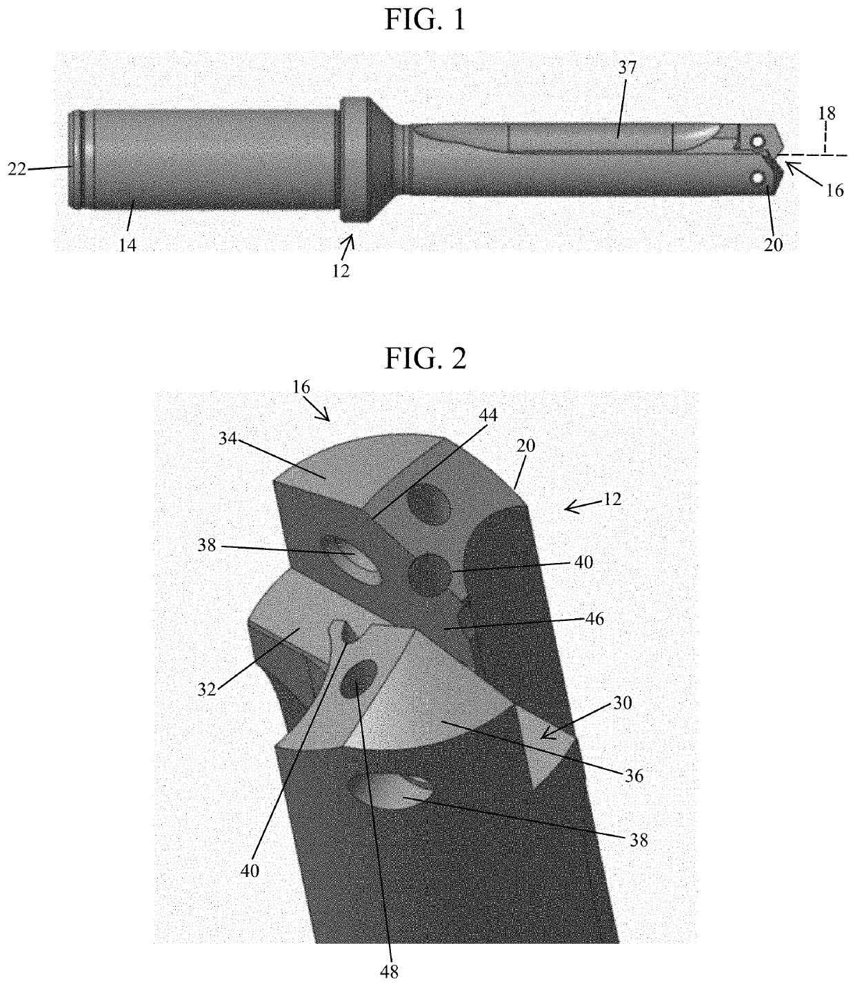
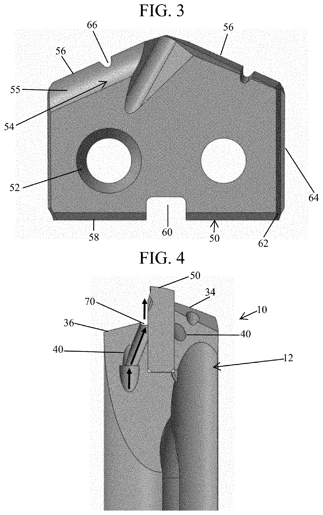
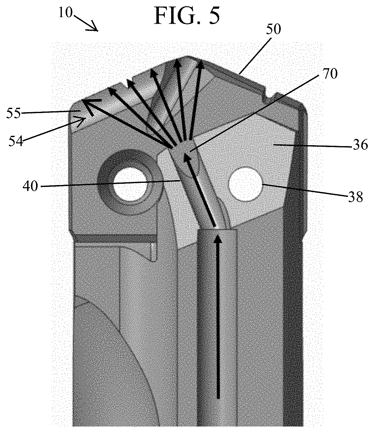
[0027]Turning now to examples of the invention, it will be noted that the coolant supply configurations provide distinct advantages in association with drilling tools used for hole making. Known coolant configurations for drills may include through coolant drills that are designed with coolant exiting on the clearance surface of the cutting geometry of the drill. This results in the coolant being directed into the bottom of the drilled hole. Other arrangements include coolant outlets exiting in the drill flute and aimed at the bottom of the hole. Such arrangements have a higher potential to disrupt chip flow through the drill flutes, and coolant is directed toward the bottom of the hole from a distance away from the cutting end of the drill. In the examples of the invention, the arrangement of coolant supply creates a superior coolant trajectory that better targets the entire rake face of the cutting geometry without disrupting chip flow. The examples are directed to improved coolan...


PUM


Abstract

There is provided a drill tool assembly for drilling metallic or other materials, comprising a holder having a mounting slot in which a cutting insert is positioned, and a through tool coolant supply system. The drilling tool system allows for the application of coolant to the rake surfaces of the cutting insert in a manner which facilitates enabling higher penetration rates while maintaining integrity of the cutting edges of the cutting insert. The drilling tool system comprises a holder having a rotational axis and mounting slot. A cutting insert with sides positioned adjacent the side surfaces of the mounting slot and cutting edges extending from the rotational axis is mounted in the slot. The insert includes rake surfaces adjacent the cutting edges that are positioned above the mounting slot. At least one coolant channel is disposed with at least one coolant outlet directed at the sides of the insert at a position below the rake surfaces. The coolant outlet is configured to disperse coolant in a curtain across the entire rake face of each cutting edge.

Description

TECHNICAL FIELD[0001]The present invention relates to a drill tool assembly for drilling metallic or other materials, comprising a holder having a mounting slot in which a cutting insert is positioned, and a through tool coolant supply system. More specifically, this invention relates to a drilling tool system that allows for the application of coolant to the rake face of the cutting insert in a manner which facilitates enabling higher penetration rates while maintaining integrity of the cutting edges of the cutting insert.BACKGROUND OF THE INVENTION[0002]In the metal cutting industry, it is highly desired to make use of coolant to achieve better tool performance. Using coolant provides lubricity, heat dissipation from the tool, and aids in chip evacuation. This results in a tool that can operate faster and achieve longer tool life. Though the use of coolant in drilling products to various industries is typical, a need still exists in the drilling tool industry for a coolant deliver...

Claims


Application Information

Patent Timeline
IPC IPC(8): B23B51/06
CPCB23B51/06B23B2200/0457B23B2200/086B23B2251/02B23B2231/24B23B2250/12B23B2200/3618B23B2251/50B23B2205/12B23B2200/128B23B51/068B23B51/00035B23B51/0684
Inventor MCKINLEY, ROBERT E.POLILLI, III, RICHARD D.LAMONICA, LOGAN J.
Owner ALLIED MASCH & ENG CORP
Why Eureka
Try Eureka