Dioptric telescope for high resolution imaging in visible and infrared bands

a dioptric telescope and visible and infrared band technology, applied in the field of optical imaging systems, can solve the problems of size and resolution capability of existing optical imaging solutions, and achieve the effect of improving the resolution capability and siz

Active Publication Date: 2021-10-21
CHOI YOUNGWAN
View PDF1 Cites 4 Cited by
  • Summary
  • Abstract
  • Description
  • Claims
  • Application Information

AI Technical Summary

Benefits of technology

[0027]In some embodiments, the reflective and cata-dioptric optical system may further comprise an inertial measurement unit connected to the first and second folding mirrors to compens

Problems solved by technology

Existing solutions to optical imaging have drawbacks wit

Method used


Image

  • Dioptric telescope for high resolution imaging in visible and infrared bands
  • Dioptric telescope for high resolution imaging in visible and infrared bands
  • Dioptric telescope for high resolution imaging in visible and infrared bands

Examples


Embodiment Construction

[0056]In the following discussion that addresses a number of embodiments and applications, reference is made to the accompanying drawings that form a part hereof, and in which is shown by way of illustration specific embodiments in which the embodiments described herein may be practiced. It is to be understood that other embodiments may be utilized, and changes may be made without departing from the scope of the disclosure.

[0057]Various inventive features are described below that can each be used independently of one another or in combination with another feature or features. However, any single inventive feature may not address all of the problems discussed above or only address one of the problems discussed above. Further, one or more of the problems discussed above may not be fully addressed by the features of each embodiment described below.

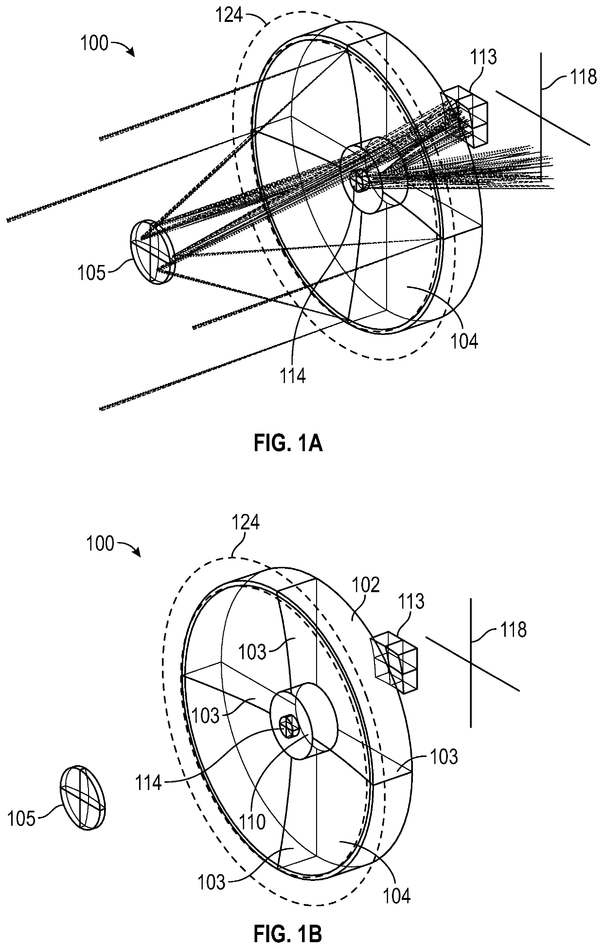
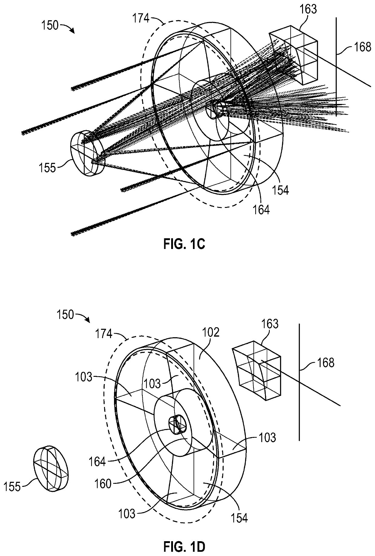
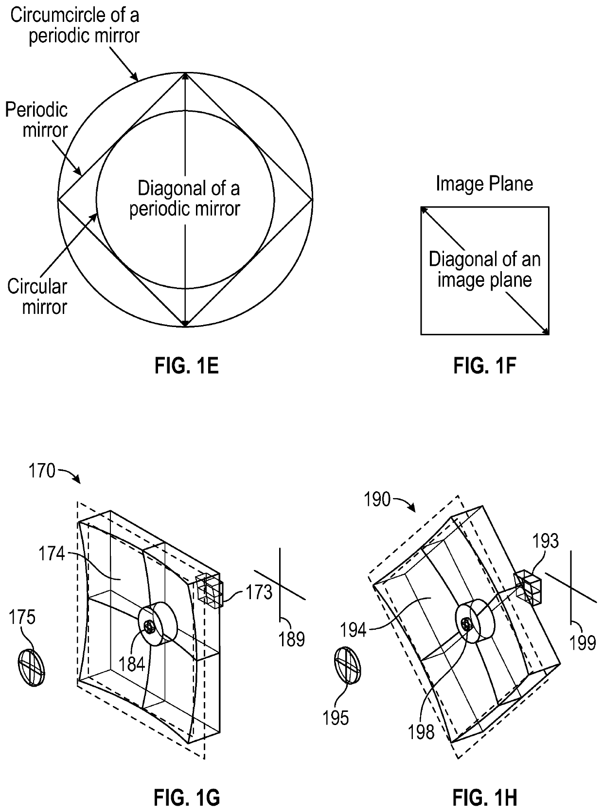
[0058]Described herein are embodiments of small volume, high resolution optical imaging systems and methods that can be used in satellites a...


PUM


Abstract

A cata-dioptric optical system for high resolution imaging in visible and infrared bands. The system includes a concave primary mirror, a convex secondary mirror, at least one beam splitter, a first folding mirror, a first group of lenses, a second group of lenses, and at least two image planes. The image planes have one or more aggregated sensors, where a first image plane receives rays from the first group of lenses and a second image plane receives rays from the second group of lenses, and at least one image plane is positioned behind the primary mirror and at a radial distance from the optical axis that is no more than the radius of the primary mirror.

Description

INCORPORATION BY REFERENCE TO ANY PRIORITY APPLICATIONS[0001]Any and all applications for which a foreign or domestic priority claim is identified in the Application Data Sheet as filed with the present application are hereby incorporated by reference under 37 CFR 1.57. For example, this application is a continuation-in-part of U.S. patent application Ser. No. 17 / 173,141, filed on Feb. 10, 2021, which is a continuation-in-part of U.S. patent application Ser. No. 16 / 989,635, filed on Aug. 10, 2020, which claims priority to U.S. Provisional Application No. 62 / 885,296, filed Aug. 11, 2019, the entire contents of each of which is hereby incorporated by reference in its entirety for all purposes and forms a part of the present specification.BACKGROUNDField[0002]This disclosure relates generally to optical imaging systems, and more specifically to small form factor four-mirror based optical imaging systems for use in satellites or aerial vehicles.Description of the Related Art[0003]Optica...

Claims


Application Information

Patent Timeline
IPC IPC(8): G02B17/06G02B23/12
CPCG02B17/0694G02B23/12G02B17/0605G02B23/06G02B17/0848G02B17/0856
Inventor CHOI, YOUNGWAN
Owner CHOI YOUNGWAN
Why Eureka
Try Eureka