
Shielded gate trench mosfet integrated with super barrier rectifier having short channel

Active Publication Date: 2021-11-11
NAMI MOS CO LTD
View PDF0 Cites 0 Cited by
  • Summary
  • Abstract
  • Description
  • Claims
  • Application Information

AI Technical Summary

Benefits of technology

The present invention offers an SGT MOSFET fused with a super barrier rectifier (SBR) on a single chip to reduce switching loss. The SBR creates a low potential barrier for the majority carrier in the MOS channel, which can be adjusted by various factors such as gate oxide thickness, P body doping concentration, and channel length. The SBR also has lower forward voltage and lower reverse leakage current than the Schottky barrier rectifier. Additionally, the SBR performs better and is more reliable at high temperatures than the Schottky barrier rectifier.

Problems solved by technology

However, the above three prior arts still encounter high Qrr (reverse recovery charge) issue as results of parasitic body diode existence, which will result in high switching loss.

Method used


Image

  • Shielded gate trench mosfet integrated with super barrier rectifier having short channel
  • Shielded gate trench mosfet integrated with super barrier rectifier having short channel
  • Shielded gate trench mosfet integrated with super barrier rectifier having short channel

Examples


Embodiment Construction

lass="d_n">[0033]In the following Detailed Description, reference is made to the accompanying drawings, which forms a part thereof, and in which is shown by way of illustration specific embodiments in which the invention may be practiced. In this regard, directional terminology, such as “top”, “bottom”, “front”, “back”, etc., is used with reference to the orientation of the Figure(s) being described. Because components of embodiments can be positioned in a number of different orientations, the directional terminology is used for purpose of illustration and is in no way limiting. It is to be understood that other embodiments may be utilized and structural or logical changes may be made without departing from the scope of the present invention. The following detailed description, therefore, is not to be taken in a limiting sense, and the scope of the present invention is defined by the appended claims. It is to be understood that the features of the various exemplary embodiments descr...


PUM


Abstract

An integrated circuit comprising an SGT MOSFET and a short channel SBR is disclosed. The SBR horizontally disposed in different areas to the SGT MOSFET on single chip creates a low potential barrier for majority carrier in MOS channel for switching loss reduction. Only one additional mask is required for integration of the short channel SBR having thinner gate oxide than the SGT MOSFET. Moreover, in some preferred embodiment, an MSO structure is applied to the shielded gate structure to further reduce the on-resistance.

Description

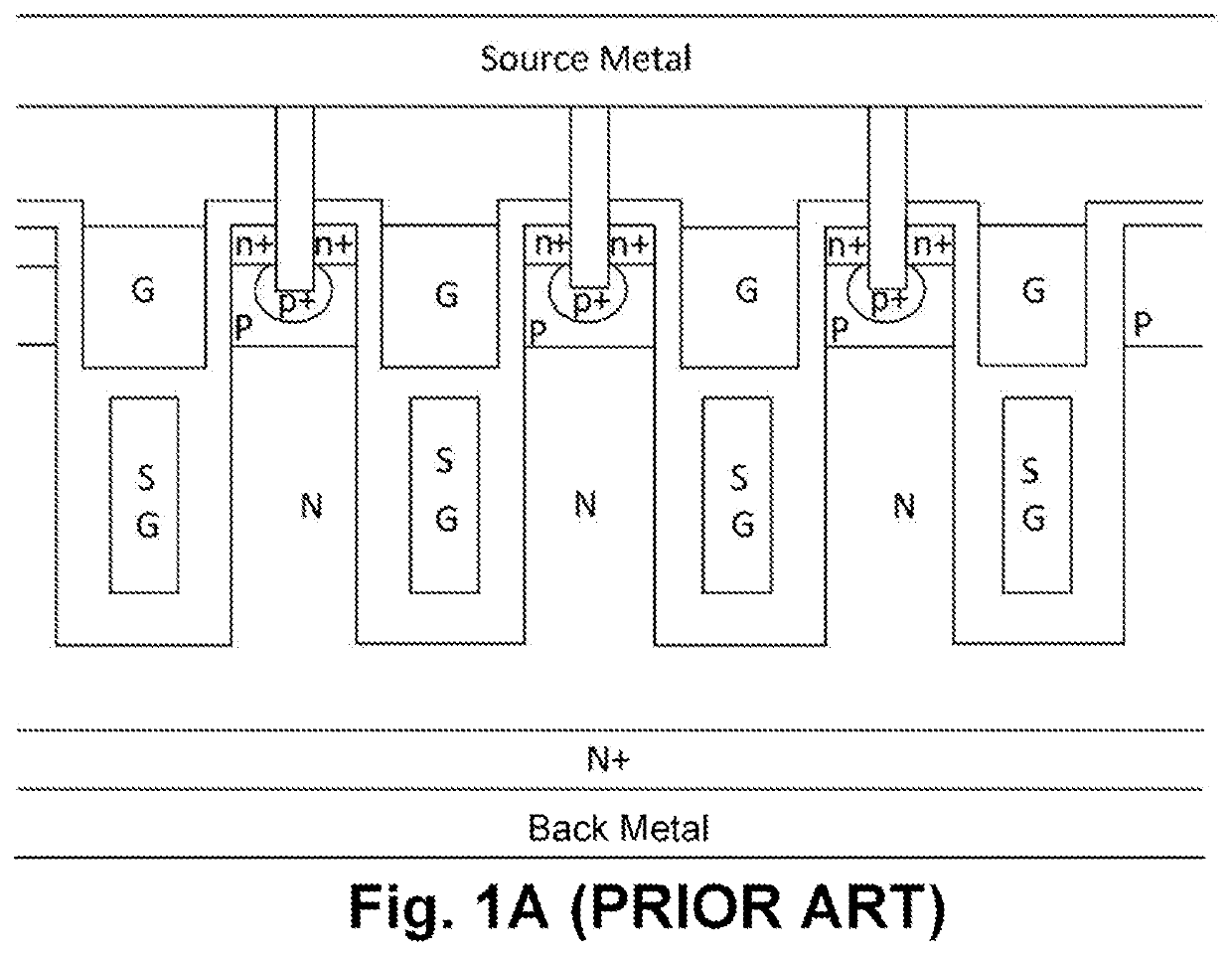
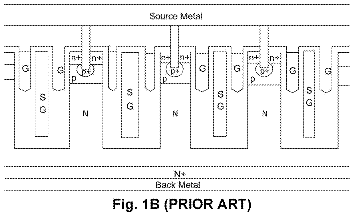
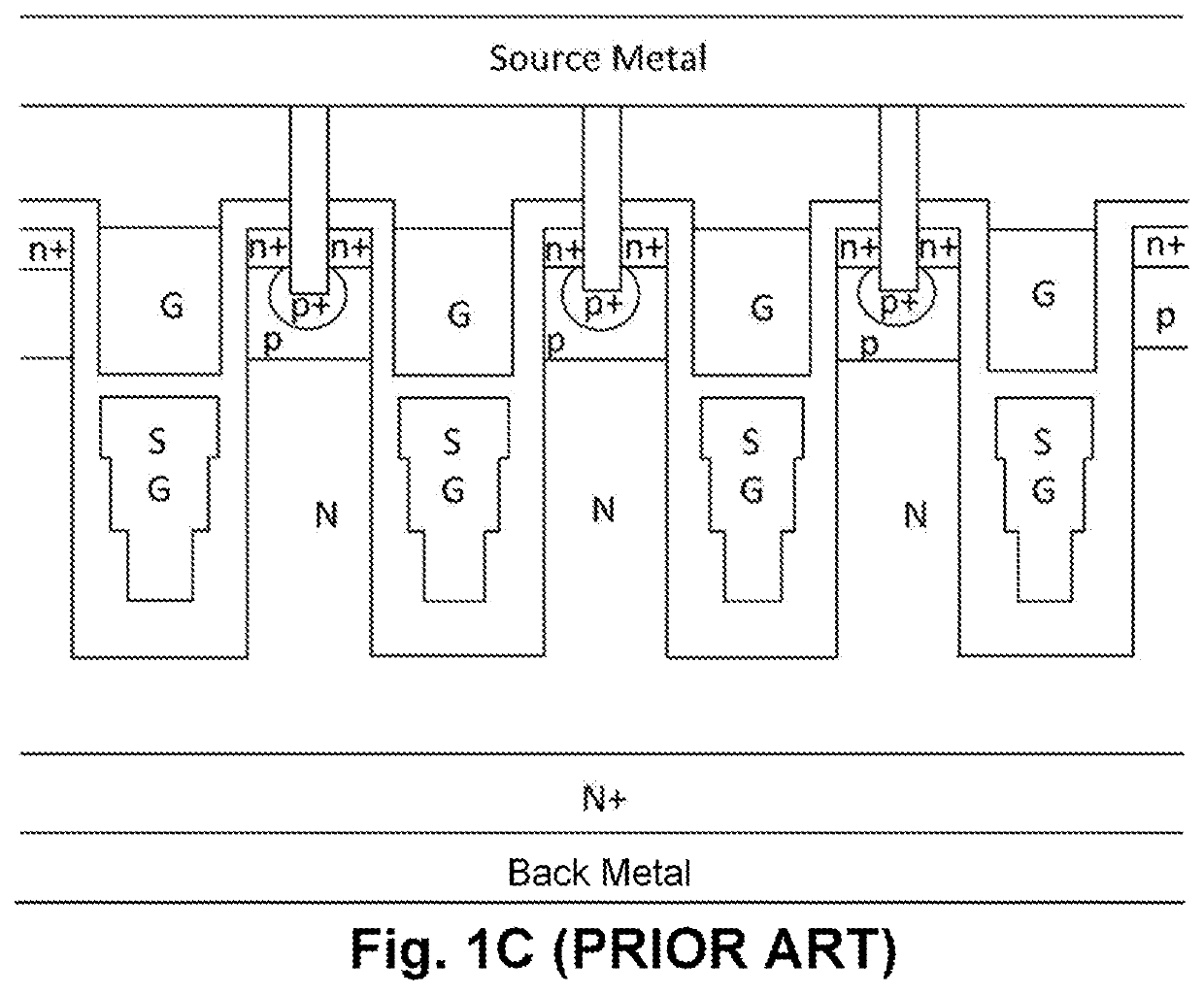
FIELD OF THE INVENTION[0001]This invention relates generally to semiconductor devices, and more particularly, to a shielded gate trench MOSFET (Metal Oxide Semiconductor Field Effect Transistor) integrated with SBR (Super Barrier Rectifier) having short channel to achieve lower on-resistance and less switching loss.BACKGROUND OF THE INVENTION[0002]Please refer to FIG. 1A and FIG. 1B for two typical types of shielded gate trench MOSFET (SGT) structure, compared with traditional single gate trench MOSFETs, the shielded gate trench MOSFETs illustrated in FIG. 1A and FIG. 1B are more attractive due to the lower gate charge and on-resistance as results of existence of charge couple region in drift region and thick oxide underneath gate oxide.[0003]To further reduce the on-resistance, a new SGT structure with multiple stepped oxide (MSO) is disclosed in U.S. Pat. No. 9,716,009 as shown in FIG. 1C, with specific on-resistance about 25% lower than the SGT MOSFETs as shown in FIG. 1A and FIG...

Claims


Application Information

Patent Timeline
IPC IPC(8): H01L29/78H01L29/06H01L29/10H01L29/40
CPCH01L29/7805H01L29/0634H01L29/7813H01L29/407H01L29/1095H01L27/0629H01L29/8613H01L29/78642H01L29/41766H01L29/0623H01L29/0878H01L29/66734H01L29/66727H01L21/26586
Inventor HSIEH, FU-YUAN
Owner NAMI MOS CO LTD
Learn More