Devices, systems, and methods for monitoring bladder function

a technology of bladder function and devices, applied in the field of devices, systems and methods for monitoring bladder function, can solve the problems that the bladder-based testing system is not able to identify or evaluate muscle motion or motion in the system, and achieve the effects of improving health and performance, improving control, and improving pelvic floor muscle strength

Pending Publication Date: 2021-11-18
AXENA HEALTH INC
View PDF0 Cites 2 Cited by
  • Summary
  • Abstract
  • Description
  • Claims
  • Application Information

AI Technical Summary

Benefits of technology

[0015]As used herein, the term “feedback” or “biofeedback” refers to information that can be used to train an individual to change physiological activity (e.g., pelvic floor muscle function) for the purpose of improving health and performance (e.g., treating, reducing, and / or preventing the occurrence of or the symptoms of a pelvic floor disorder (PFD)). (Bio)Feedback may also include information collected by a device of the invention during daily monitoring, e.g., in substantially real-time, while a user performs her daily activities. The information can be reviewed substantially in real-time or can be accessed for review at a later time. Instruments, such as a device of the invention, can be used to measure physiological activity, such as muscle activity (e.g., movement and pressure), pressure (e.g., bladder or vaginal pressure), muscle quality, and vaginal canal pH, temperature, and humidity, and to provide this information as biofeedback to the individual. Instruments, such as a device of the invention, can also be used to measure the level of a molecule, e.g., the level of a hormone and / or the level of a toxin, and to provide this information as biofeedback to the individual. The presentation of this information to the individual can be by a visual, audible, or tactile signal, and can support a desired physiological change (e.g., improved pelvic floor muscle strength, control, and quality).

Problems solved by technology

However, these methodologies often provide incomplete information about the nature of the bladder function, do not always effectively differentiate between the various types of urinary incontinence, and can be subject to human error.
Although urodynamic testing can be used to evaluate changes in bladder pressures and in leakage due to pressure gradients, urodynamic testing systems are not able to identify or evaluate muscle motion or motion in the system due to Valsalva.

Method used


Image

  • Devices, systems, and methods for monitoring bladder function
  • Devices, systems, and methods for monitoring bladder function
  • Devices, systems, and methods for monitoring bladder function

Examples


example 1

Urodynamic Testing with a Positional Sensor Enabled Urodynamic Catheter

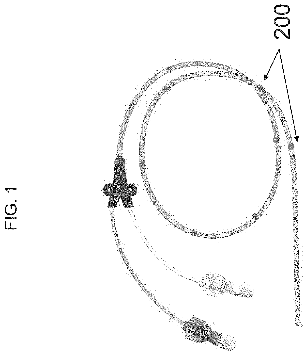
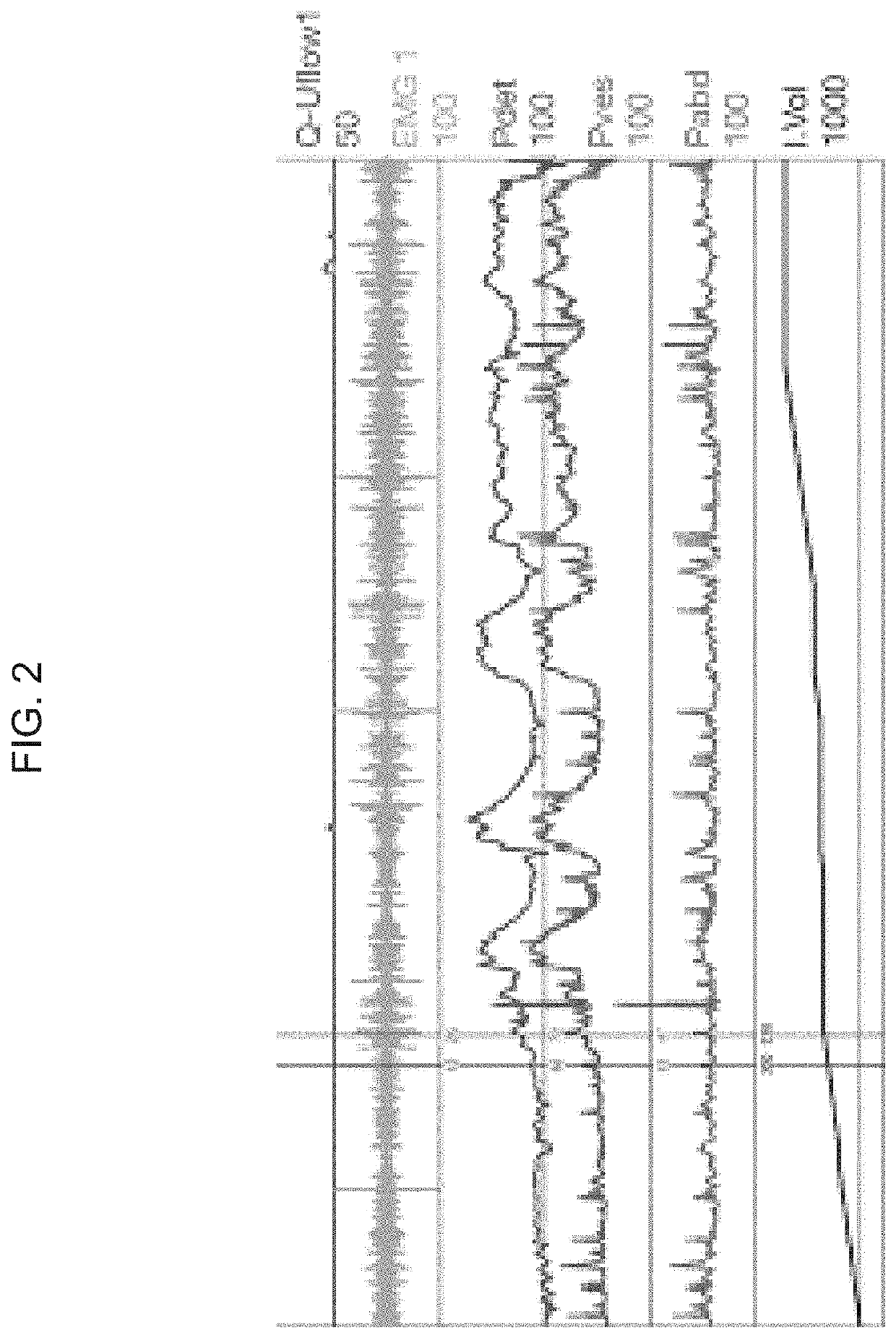
[0106]A female subject with urinary incontinence uses a positional sensor enabled urodynamic catheter (FIG. 1) during urodynamic testing. The urodynamic catheter includes a plurality of MEMS accelerometers located along a length of the device. A physician inserts the catheter in the subject and the subject urinates. The catheter measures flow and electrical activity of the muscles and nerves of the pelvic floor using electromyography (FIG. 2). The catheter also measures detrusor pressure, vesicular pressure, abdominal pressure and the volume of fluid in the bladder. The positional sensors on the catheter provide detailed visual information during bladder filling, emptying, and Valsalva. The characteristic patterns observed from the readout of the accelerometers indicates that the subject has urethral hypermobility.

[0107]An intravaginal and / or intrarectal device can also be used during urodynamics testing to obtai...

example 2

Using an Algorithm to Detect Pelvic Floor Movement

[0108]An intravaginal device having a plurality of MEMS accelerometers was inserted into the vagina of a female subject and the subject was asked to perform a series of pelvic floor movements (e.g., pelvic floor lift, pelvic floor relaxation, Valsalva maneuver, sustained pelvic floor lift, and serially repeated pelvic floor lift). Sensor angle (relative to the horizon) and position data from each MEMS accelerometer was collected. The angle data from each sensor was plotted as a function of time (FIG. 6).

[0109]Two composite scores, Y1 and Y2, were calculated from the angles (A) of sensors S5-S7:

Y1=A5+A6+0.6×A7

Y2=A5+A6−0.8×A7

A moving average of Y1 and Y2 (Y1_movmean and Y2_movmean) was calculated from three consecutive samples of Y1 and Y2. The moving average filter was used to reduce noise and minimize false positives. The filtered composite scores were plotted versus time (FIG. 7A) and a derivative of these data was plotted as a chan...

example 3

Detection of Pelvic Floor Movements During Daily Activities as a Measure of a Health State of a User

[0111]A user can insert an intravaginal device having a plurality of MEMS accelerometers into her vagina and the device can detect pelvic floor movements (e.g., pelvic floor lift, pelvic floor relaxation, Valsalva maneuver, sustained pelvic floor lift, and serially repeated pelvic floor lift) during her daily activities. A processor in the device, or in a peripheral device, such as a smartphone or wearable device (e.g., a watch) can process the data to calculate the occurrence of a pelvic floor event. Each MEMS accelerometer emits a signal corresponding to the position and sensor angle relative to the horizon. The angle data from each sensor is plotted as a function of time. The strength of the signal from each sensors is denoted by the change in angle (angle during pelvic floor lift—angle during pelvic floor relaxation). This signal strength is used to determine which sensors provide...


PUM


Abstract

Featured are urodynamic catheters, intravaginal devices, and intrarectal devices, systems and kits thereof, and methods of using the devices, systems, and kits to observe pelvic floor movements in order to monitor bladder function in order to diagnose, treat, or prevent urinary incontinence disorders, such as urge incontinence and stress incontinence.

Description

BACKGROUND[0001]Urinary incontinence occurs in both men and women and is associated with weakened or tense (e.g., hypertonic) pelvic floor (PF) muscles. Many common factors contribute to the weakening or tightening of the pelvic floor muscles in women, such as pregnancy, vaginal childbirth, pelvic surgery, aging, genetic predisposition, neurological disease, and weight gain. For men, urinary incontinence is often caused by an enlarged prostate. Furthermore, urinary incontinence is often divided into three types: stress urinary incontinence (SUI), urgency urinary incontinence, and mixed incontinence.[0002]Current methods for diagnosing urinary incontinence include the monitoring of bladder function by using urodynamic testing and / or voiding diaries. However, these methodologies often provide incomplete information about the nature of the bladder function, do not always effectively differentiate between the various types of urinary incontinence, and can be subject to human error. Alth...

Claims


Application Information

Patent Timeline
Patent Type & Authority Applications(United States)
IPC IPC(8): A61B5/20A61B5/00A61B5/06A61B5/07
CPCA61B5/202A61B5/6856A61B5/067A61B5/7435A61M2025/0166A61B5/07A61B5/205A61B2562/028A61B5/7475A61B5/20A61B5/6852A61B2562/043
Inventor BEER, MARC D.PULLIAM, SAMANTHA J.MCKINNEY, JESSICA L.
Owner AXENA HEALTH INC
Why Eureka
Try Eureka