Dental probe

a technology of optical probes and probes, applied in the field of optical tooth characterization, can solve the problems of only being effective, restorations such as fillings, crowns or bridges, cannot be transparent to light of wavelengths of interest, and restorations pose significant problems for any measurement using electromagnetic radiation, so as to improve the signal-to-noise ratio, improve the sensitivity and specificity of the method, and reduce the diameter of the receiver and the emitter.

Active Publication Date: 2021-12-02
DENTSPLY SIRONA INC
View PDF0 Cites 1 Cited by
  • Summary
  • Abstract
  • Description
  • Claims
  • Application Information

AI Technical Summary

Benefits of technology

[0030]Furthermore, the present invention is based on the recognition that it is possible to provide specific mechanical measures which significantly improve the sensitivity and specificity of the method of DE19649689. In particular, although a reduction of the diameter of the receiver and emitter deteriorates the signal to noise ratio of the device, it is possible to improve the signal to noise ratio by reducing the influence of ambient light, any restoration. hard dental tissue and soft dental tissue other than the dental pulp by a specific dental probe. According to the present invention, the apical-coronal diameter of the light emitter surface and the light receiver surface is at most 1200 μm in the direction normal to the optical path so that the dental probe may be positioned on a limited space of the tooth below a dental crown, without covering or excessively approaching soft dental tissue. The dental probe has a light shielding spacer member adjacent to the optical path for establishing and maintaining a distance between the gum line and the optical path at the receiver surface. Additionally, the dental probe may have a pressing member for engaging the gingiva by applying pressure onto the gum when the receiver surface is positioned on the tooth, thereby providing an anaemic condition of the gingiva.

Problems solved by technology

Moreover, conservative procedures aimed at preserving pulp vitality, can only be effective if the status of the pulp is accurately assessed.
However a restoration such as a filling, crown or bridge is not transparent to light of a wavelength of interest.
Therefore, a restoration poses significant problems to any measurement using electromagnetic radiation, in particular when the restoration extends as far as below the gum line.
Unfortunately, the sensation can be unpleasant or painful to the patient.
Moreover, the successful stimulation of nerves in the pulp does not exclude the possibility of pulp disease.
Furthermore, stimulating a tooth without also stimulating surrounding gingival tissues or nearby teeth is difficult.
Accordingly, any thermal and the electrical sensitivity tests have a relatively high rate of false positives and false negatives.
Although the test may be carried out by a simple and inexpensive procedure, the quality of the results is not ideal.
Accordingly, the cold test gives rise to false positive results where a non-vital tooth appears to respond positively to testing.
Therefore, there is a risk that a non-vital tooth is left untreated.
Moreover, the cold test may also give false negative results meaning that a vital tooth has not responded positively to testing.
As a result, a vital tooth may be subject to an unnecessary and costly endodontic treatment.
The probe body is large as compared to a tooth and cannot be reliably used for determining the vitality of a tooth having been restored by a filling, crown or bridge.
In particular, the probe body is large as compared to a tooth and cannot be reliably used for determining the vitality of a tooth having been restored by a filling, crown or bridge.
Therefore, and despite continuous efforts in the field, the concept as disclosed by DE19649689 did not allow the development of any useful clinical method for decades.
None of the prior art addresses the problem of determining the vitality of a restored tooth having a restoration extending close to or beyond the gum line.

Method used


Image

  • Dental probe
  • Dental probe
  • Dental probe

Examples


first embodiment

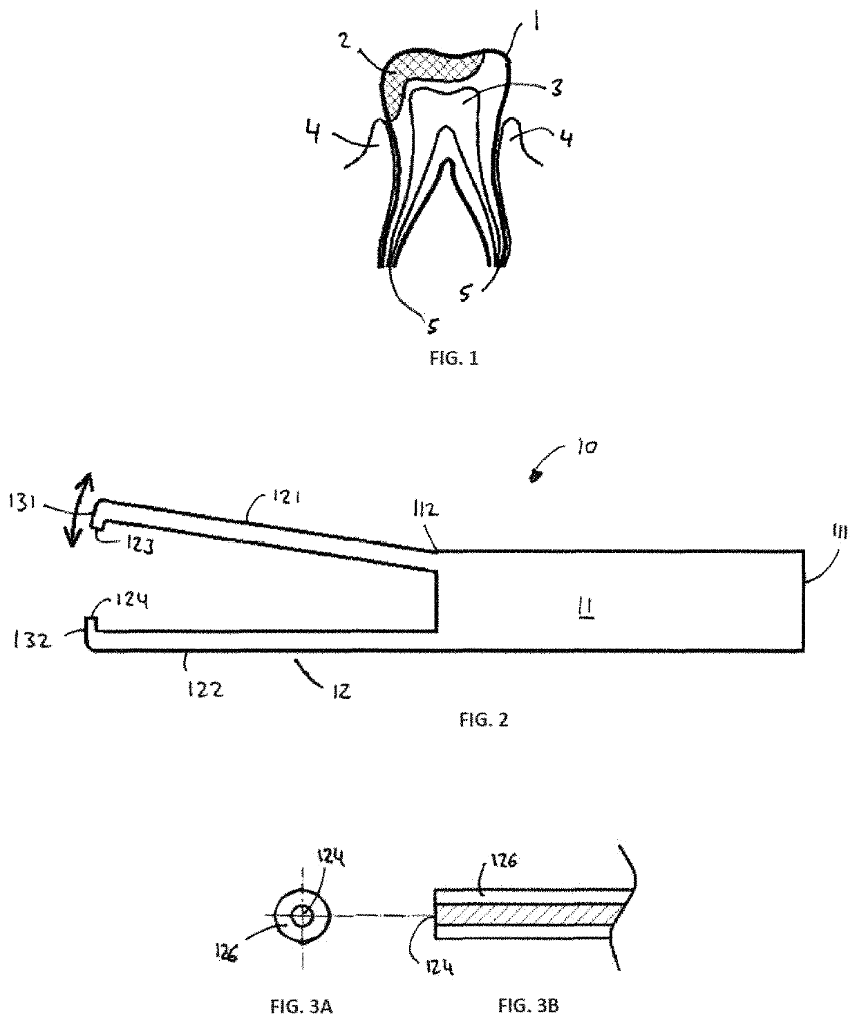
[0052]The present invention provides a dental probe for determining the vitality of a tooth, in particular a tooth previously having been restored by a filling, crown or bridge. The dental probe is adapted to be used in the mouth of the patient. Specifically, the dental probe is adapted to be positioned consecutively on every tooth in the buccal / oral cavity. Given the orientation of the teeth in each of the four dental quadrants, the design of the dental probe, in particular the design of the emitter surface and the receiving surface preferably has symmetry properties. a mirror plane is present between the emitter surface and the receiving surface. According to a further embodiment, a first mirror plane is present between the emitter surface and the receiving surface and a second mirror plane perpendicular to the first mirror plane is furthermore present, whereby the emitter surface and the receiving surface have two-fold symmetry.

[0053]Moreover, the dental probe is adapted to be s...

second embodiment

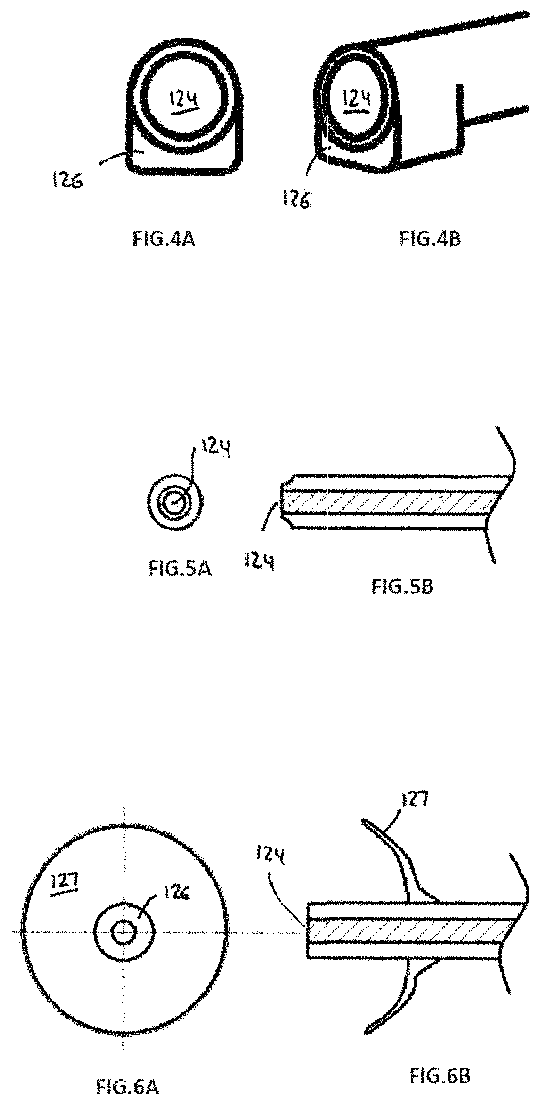
[0109]FIGS. 4A and 4B shows a partial view of a dental probe according to the present invention, which includes a light receiving surface 124 and a light shielding spacer member 126 adjacent to the optical path for establishing and maintaining a distance between the gum line and the optical path at the receiver surface 124.

[0110]FIG. 4A shows a front view of the receiver surface 124 and spacer member 126. The diameter of the circular receiver surface 124 is at most 1200 μm. The receiver surface is at the distal end of a light guide. Accordingly, the receiver surface may be easily placed on the surface of a tooth. In order to keep a defined distance between the gum line and the receiver surface and in order to shield the receiver surface from scatter light from the gingiva, a spacer member 126 is provided.

[0111]FIG. 4B shows a perspective view of the receiver surface 124 and spacer member 126 shown in FIG. 4A. As shown, the front surface of the spacer member and the receiver surface ...

third embodiment

[0112]FIGS. 5A and 5B shows a partial view of a dental probe according to the present invention, which includes a light receiving surface and a pressing member for engaging the gingiva by applying pressure onto the gum when the receiver surface is positioned on the tooth, thereby providing an anaemic condition of the gingvia. The pressing member and the light shielding spacer member are integral parts of a combination member adjacent to the optical path for establishing and maintaining a distance between the gum line and the optical path at the receiver surface.

[0113]FIG. 5A shows a front view of the receiver surface 124 and spacer member 126. The diameter of the circular receiver surface 124 is at most 1200 μm. The receiver surface is at the distal end of a light guide. Accordingly, the receiver surface may be easily placed on the surface of a tooth. In order to keep a defined distance between the gum line and the receiver surface and in order to shield the receiver surface from sc...


PUM

PropertyMeasurementUnit
distanceaaaaaaaaaa
apical-coronal diameteraaaaaaaaaa
diameteraaaaaaaaaa

Abstract

A dental probe for determining the vitality of a tooth, comprising a light emitter and a light receiver, wherein the light emitter emits light from an emitter surface adapted to be positioned on a hard dental surface of a tooth, wherein the light receiver collects light incident on a receiver surface adapted to be positioned on a hard dental surface of the tooth so that the optical path of the light emitted from the light emitter passes at least through a portion of the pulp chamber of the tooth. The light receiver includes a light shielding spacer member adjacent to the optical path for establishing and maintaining a distance of at least 50 μm between the gum line and the optical path at the receiver surface. The light emitter further a light shielding spacer member adjacent to the optical path for establishing and maintaining a distance between the gum line and the optical path at the emitter surface, wherein the light shielding spacer member establishes and maintains a distance of at least 50 μm between the gum line and the optical path at the emitter surface, and in that an apical-coronal diameter of the light emitter surface and the light receiver surface is at most 1200 μm in the direction normal to the optical path.

Description

THE CROSS-REFERENCE TO RELATED APPLICATIONS[0001]This application is a continuation of U.S. application Ser. No. 16 / 092,046, filed Oct. 8, 2018 (now abandoned), which is a national phase of PCT / EP2017 / 058453, filed Apr. 7, 2017.FIELD OF THE INVENTION[0002]The present invention relates to an optical tooth characterization based on, an objective examination of the pulp of the tooth. Specifically, the present invention relates to a dental probe for determining the vitality of a tooth, in particular of a tooth previously having been restored by a filling, crown or bridge, for example. The dental probe is also useful for determining additional parameters including a bacterial, inflammation, and / or health status by irradiation of light through a portion of the pulp chamber. Accordingly, the present invention allows optical tooth characterization under crowns and other restorations.[0003]Advantageously, the dental probe comprises a light emitter surface and / or a light receiver surface, whi...

Claims


Application Information

Patent Timeline
Patent Type & Authority Applications(United States)
IPC IPC(8): A61B5/00A61B5/026
CPCA61B5/0088A61B5/0261A61C1/088A61B2562/0238A61B5/682
Inventor ERTL, THOMASKARAZIVAN, NAIMSAVIC, ALEXANDER
Owner DENTSPLY SIRONA INC
Why Eureka
Try Eureka