Gyroscopically stabilised legged robot

a gyroscope and gyroscope technology, applied in the direction of manufacturing tools, process and machine control, instruments, etc., can solve the problems of significant increase in design, control and actuation cost and complexity, and the inability to move appendages around humans, etc., and achieve the effect of rotating the gyroscope axes

Pending Publication Date: 2021-12-09
THE UNIV OF QUEENSLAND
View PDF0 Cites 1 Cited by
  • Summary
  • Abstract
  • Description
  • Claims
  • Application Information

AI Technical Summary

Benefits of technology

The patent describes a system that controls the orientation of a robot using a gyroscope. The system includes an orientation stability subsystem that stabilizes the robot's position based on the detected angle of its movement. It also includes a relaxation control subsystem that reduces bias moments and increases the speed of the system's rotation. Overall, the system improves the robot's stability and reduces its movements, allowing it to better navigate its environment.

Problems solved by technology

This mobility comes at significantly increased design, control and actuation cost and complexity; this is highlighted by recent advancements in humanoid robotics, where a walking platform may cost hundreds of thousands of dollars.
The rationale for avoiding complex articulated arms / pendulums for balance-keeping is similar, with the additional consideration that moving appendages may not be appropriate for use around humans where they may pose a hazard.
This requires high performance sensing and actuation to place the limbs in the appropriate position at each point in time, resulting in expensive walking machines.
A key limitation of reaction wheels, however, is that the operation of common electric motors and bearings puts an upper-limit on the achievable speed of the wheel, and thus the sustainment of acceleration—at maximum speed, the reaction wheel saturates and no further momentum may be cancelled.
Increasing the mass of the flywheel allows for greater momentum transfer prior to saturation, but at the cost of added weight that must be carried.
However, the gait and precession of the gyroscope had to be tightly synchronized and the use of this strategy imposed restrictive constraints on the gaits available for use.
However, this uses a complex twin-type CMG to provide a torque in a single axis only.

Method used


Image

  • Gyroscopically stabilised legged robot
  • Gyroscopically stabilised legged robot
  • Gyroscopically stabilised legged robot

Examples


Embodiment Construction

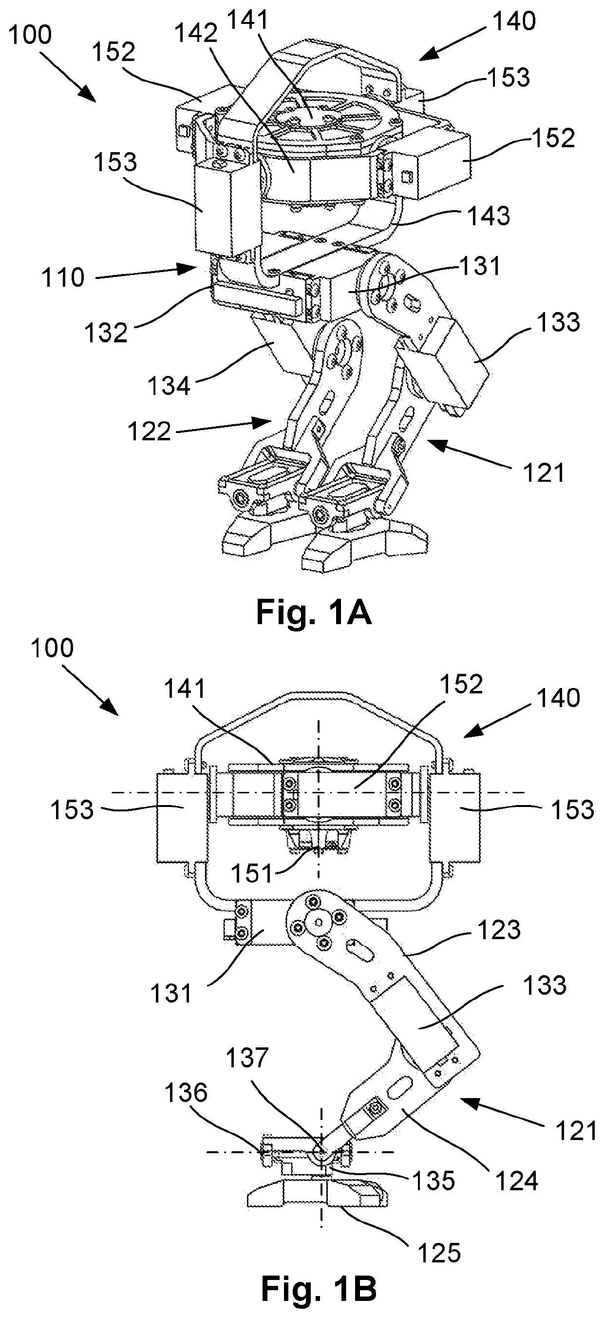
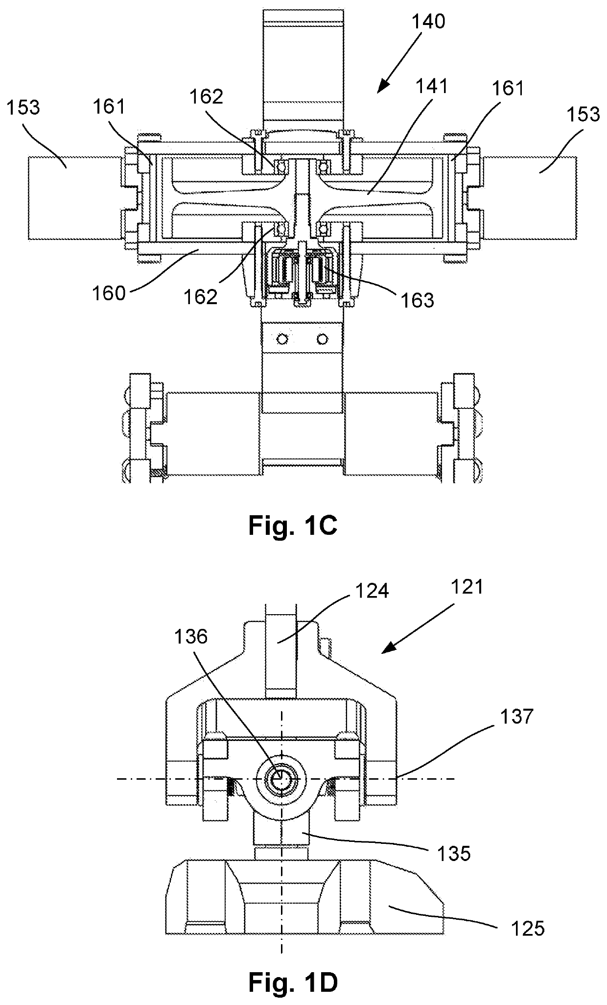
[0065]An example of a gyroscopically stabilised legged robot 100 will now be described with reference to FIGS. 1A to 1D.

[0066]In broad terms, the robot 100 includes a body 110, and a number of legs 121, 122 coupled to the body 110 and configured for providing legged locomotion of the robot across a surface in use. It will be appreciated that the particular form of legged locomotion will depend on the number and construction of the legs. Whilst the following description will primarily focus on a two-legged (i.e. bipedal) embodiment of the robot 100 as shown in FIGS. 1A to 1D, which is capable of a walking locomotion, it should be understood that the techniques set out below can be applied to robots having any number of legs, ranging from one legged hopping robots to walking robots having more than two legs.

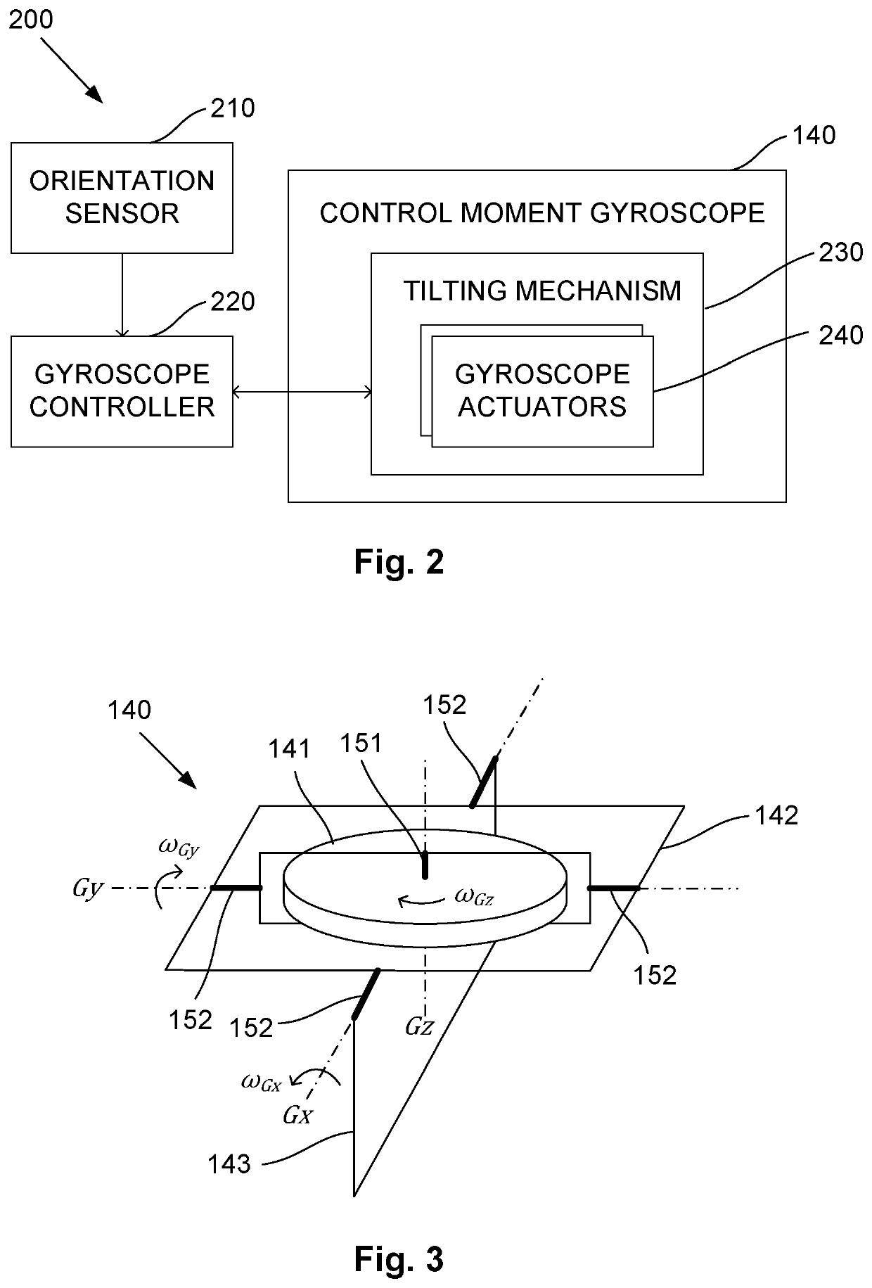
[0067]The robot 100 is adapted to at least partially stabilise the angular orientation of the body 110 during its legged locomotion. FIG. 2 is a block diagram of an example of an o...


PUM


Abstract

A gyroscopically stabilised legged robot including: a body; a number of legs coupled to the body and configured for providing legged locomotion of the robot across a surface in use; an orientation sensor for detecting an angular orientation of the body; a control moment gyroscope mounted on the robot, the control moment gyroscope including a rotor that spins around a rotor spin axis in use, and a tilting mechanism for supporting the rotor relative to the robot, the tilting mechanism being configured to rotate the rotor spin axis about two gyroscope rotation axes to thereby generate respective gyroscopic reaction torques; and a gyroscope controller configured to control operation of the tilting mechanism based at least in part on the detected angular orientation of the body, such that gyroscopic reaction torques are generated to at least partially stabilise the angular orientation of the body during the legged locomotion of the robot.

Description

BACKGROUND OF THE INVENTION[0001]The present invention relates to a gyroscopically stabilised legged robot.DESCRIPTION OF THE PRIOR ART[0002]Bipedal robots promise mobility capabilities on par with humans, with the attendant ability to navigate difficult terrain inaccessible to wheeled vehicles or unwieldy for quadrupeds or hexapods. This mobility comes at significantly increased design, control and actuation cost and complexity; this is highlighted by recent advancements in humanoid robotics, where a walking platform may cost hundreds of thousands of dollars. Such robots use sophisticated motion sensing and control combined with very capable actuators to provide fast application of required balance forces through contact with the ground. However, there are lower-end tasks such as compound / area security, urban patrol, search and rescue, and domestic applications where a more economical, if less capable, dynamic bipedal walking machine may be useful. These robots would necessarily us...

Claims


Application Information

Patent Timeline
Patent Type & Authority Applications(United States)
IPC IPC(8): B25J19/00B62D37/06B62D57/02B25J9/16B25J13/08B62D57/032
CPCB25J19/0008B62D37/06B62D57/032B25J9/162B25J13/089B62D57/022G05D1/0891B62D57/024B25J9/0009G01C19/02G01C19/065G01C19/30B25J13/088
Inventor POUNDS, PAULINE EDITH IYAN
Owner THE UNIV OF QUEENSLAND
Why Eureka
Try Eureka