Abnormality cause determining device, vehicular control device, and vehicular control system

a technology of anomalous causes and determining devices, applied in mechanical devices, instruments, transportation and packaging, etc., can solve the problems of high demands for map updates, and the effect of increasing the amount of data for upda

Pending Publication Date: 2021-12-16
TOYOTA JIDOSHA KK
View PDF0 Cites 1 Cited by
  • Summary
  • Abstract
  • Description
  • Claims
  • Application Information

AI Technical Summary

Benefits of technology

[0026]With the vehicular control system having this configuration, when the value of the output variable associated with each of a plurality of vehicles is not valid, the map data is updated. Accordingly, in comparison with a case in which only the value of the output variable of a single vehicle is handled, an amount of data for update can be readily increased and the map data can be used as data for accurately calculating the value of the output variable in actual traveling of the vehicle.

Problems solved by technology

When an abnormality occurs in an onboard component including an electromagnetic actuator, the behavior of a current actually flowing in the electromagnetic actuator is likely to be affected.
With the abnormality cause determining device having the aforementioned configuration, when a single map is used regardless of the type of shift of the gear shift ratio, the demands with regard to the map are high.
Accordingly, when a single map is used regardless of the torque, the demands with regard to the map are high.
In the abnormality cause determining device having the aforementioned configuration, the cause variable may include a decrease in controllability of the solenoid valve due to bubbles included in a hydraulic fluid of the gear shifting device, a temporary stick abnormality which is an abnormality temporarily occurring in an operation of the solenoid valve due to temporary mixing of foreign matter into the solenoid valve, and a regular stick abnormality which is an abnormality occurring regularly in the operation of the solenoid valve due to mixing of foreign matter into the solenoid valve.

Method used


Image

  • Abnormality cause determining device, vehicular control device, and vehicular control system
  • Abnormality cause determining device, vehicular control device, and vehicular control system
  • Abnormality cause determining device, vehicular control device, and vehicular control system

Examples


first embodiment

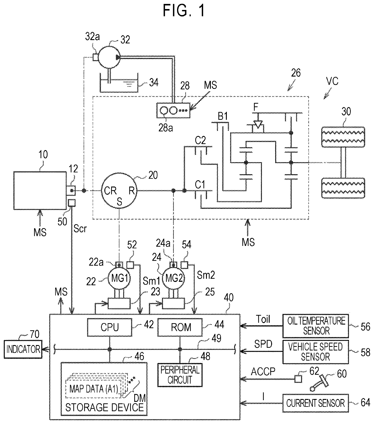
[0047]Hereinafter, a first embodiment will be described with reference to the accompanying drawings. As illustrated in FIG. 1, a power split device 20 is mechanically connected to a crank shaft 12 of an internal combustion engine 10. The power split device 20 splits power of the internal combustion engine 10, a first motor / generator 22, and a second motor / generator 24. The power split device 20 includes a planetary gear mechanism, the crank shaft 12 is mechanically connected to a carrier CR of the planetary gear mechanism, a rotation shaft 22a of the first motor / generator 22 is mechanically connected to a sun gear S, and a rotation shaft 24a of the second motor / generator 24 is mechanically connected to a ring gear R. An output voltage of a first inverter 23 is applied to terminals of the first motor / generator 22. An output voltage of a second inverter 25 is applied to terminals of the second motor / generator 24.

[0048]In addition to the rotation shaft 24a of the second motor / generator...

second embodiment

[0087]FIG. 8 illustrates a configuration of a system according to the In FIG. 8, elements corresponding to the elements illustrated in FIG. 1 will be referred to by the same reference signs for the purpose of convenience, and description thereof will not be repeated. As illustrated in FIG. 8, symptom detection data DPD in addition to the map data DM is stored in the storage device 46 of a vehicle VC(1). The control device 40 includes a communication device 47 and can communicate with a data analysis center 90 via an external network 80 using the communication device 47.

[0088]The data analysis center 90 collects and analyzes data transmitted from a plurality of vehicles VC(1), VC(2), . . . as big data DB. The data analysis center 90 includes a CPU 92, a ROM 94, a storage device 96, and a communication device 97, which can communicate with each other via a local network 99. The storage device 96 is a nonvolatile memory which is electrically rewritable, and stores big data DB.

[0089]In...

third embodiment

[0110]In this way, it is possible to decrease a calculation load of the CPU 42 by causing the outside of the vehicle VC(1) to perform the process of S52. When the result of determination of a cause in the processes of S52 to S54 is erroneous, the map data DM can be updated. Particularly, a result of determination of a cause using a map defined by the map data DM for an abnormality having occurred in various driving situations by various users after the vehicles VC(1), VC(2), . . . have been shipped can be verified.

[0111]Correspondence in elements between the claims and the embodiments will be described below. The correspondence is described below in the order of description in the “SUMMARY.” An example of an abnormality cause determining device is the control device 40 illustrated in FIG. 1 or 8 or the data analysis center 90 illustrated in FIG. 11. An example of an electromagnetic actuator is the solenoid valve 28a. An example of an execution device is the CPU 42 or the ROM 44 ill...


PUM


Abstract

An abnormality cause determining device that is applied to a vehicle including an electromagnetic actuator includes a storage device and an execution device. The storage device is configured to store map data which is data for defining a map. The map includes a current variable which is a variable indicating a current flowing actually in the electromagnetic actuator as an input variable and includes a cause variable which is a variable indicating a cause of an abnormality of an onboard unit including the electromagnetic actuator as an output variable. The execution device is configured to perform an acquisition process of acquiring a value of the input variable based on a detection value from a sensor which is mounted in the vehicle and a calculation process of calculating a value of the output variable by inputting the value of the input variable to the map.

Description

CROSS-REFERENCE TO RELATED APPLICATION[0001]This application claims priority to Japanese Patent Application No. 2020-103626 filed on Jun. 16, 2020, incorporated herein by reference in its entirety.BACKGROUND1. Technical Field[0002]The disclosure relates to an abnormality cause determining device, a vehicular control device, and a vehicular control system.2. Description of Related Art[0003]For example, Japanese Unexamined Patent Application Publication No. 2016-219569 (JP 2016-219569 A) discloses a device that determines whether an abnormality has occurred in a linear solenoid based on a current flowing in the linear solenoid.SUMMARY[0004]When an abnormality has occurred in a linear solenoid, a linear solenoid drive device needs to be disassembled to identify details of a position at which the abnormality has occurred.[0005]The disclosure provides an abnormality cause determining device, a vehicular control device, and a vehicular control system that can identify details of a positio...

Claims


Application Information

Patent Timeline
Patent Type & Authority Applications(United States)
IPC IPC(8): G07C5/08F16H61/12F16H61/02
CPCG07C5/0808G07C5/0816F16H2061/1216F16H61/0204F16H2061/1288F16H61/12B60R16/0232Y02T10/62F16H2061/1208F16D2500/5108F16H2061/1284F16H2061/1224F16H61/2807F16D2500/5114
Inventor TABATA, ATSUSHIOKUDA, KOICHIIMAMURA, KENITO, SHINICHIFUJII, KOTA
Owner TOYOTA JIDOSHA KK
Why Eureka
Try Eureka