A RF connector comprising a flat central contact which end is shaped as a fork to receive the contact pin of a complementary connector and a solid insulating structure configured to guide the contact pin

Active Publication Date: 2021-12-16
RADIALL SA
0 Cites 2 Cited by

AI-Extracted Technical Summary

Problems solved by technology

The major drawback is the great limitation on the axial and radial misalignments allowed for these connections.
However, all the known board-to-board connections do present a significant number of drawbacks due to the conception of the RF coaxial components.
Firstly, a slotted sleeve has not only high production cost, but also has high processing requirements. More particularly, the central female contact has an inner hole at the end, and in most cases, the inner hole is a blind hole. After the turning process, the fluid, that is used for cutting, needs to be cleaned, which is difficult to be properly cleaned, and the inner hole is black after the heat treatment when incorrect cleaning and presence of residues. When applying an electroplating process, the inner hole is not easily plated with a plating layer to cover the residues. Besides, at the time of electroplating, the central female contact has a large difference in current density between the interior of hole and the exterior of the hole. Generally, the current density...

Benefits of technology

[0045]In an advantageous embodiment, the solid insulating structure has a substantially cylindrical cavity radially extended by two diametrically opposite slots in each of which one of the two branches of the fork is...

Abstract

The application relates to a connector, intended to transmit radio frequency RF signals, of longitudinal axis X, including: a central contact under the form of an elongated flat strip which at least one of its ends is shaped as a fork with two flexible branches to define inwardly a cavity extending along the axis X for receiving a contact pin of one complementary connector, the two flexible branches of the fork being configured such that to apply a contact force to the contact pin; at least one solid insulating structure in which the central contact is mechanically retained, one of its ends of the insulating structure being configured to let the two flexible branches to move freely radially and to guide the contact pin while enabling its swivelling when inserted into the cavity (C) defined by the fork.

Application Domain

Technology Topic

Image

  • A RF connector comprising a flat central contact which end is shaped as a fork to receive the contact pin of a complementary connector and a solid insulating structure configured to guide the contact pin
  • A RF connector comprising a flat central contact which end is shaped as a fork to receive the contact pin of a complementary connector and a solid insulating structure configured to guide the contact pin
  • A RF connector comprising a flat central contact which end is shaped as a fork to receive the contact pin of a complementary connector and a solid insulating structure configured to guide the contact pin

Examples

  • Experimental program(1)

Example

[0056]Other advantages and features of the invention will become more apparent on reading the detailed description of exemplary implementations of the invention, given as illustrative and non-limiting examples with reference to the following figures in which:
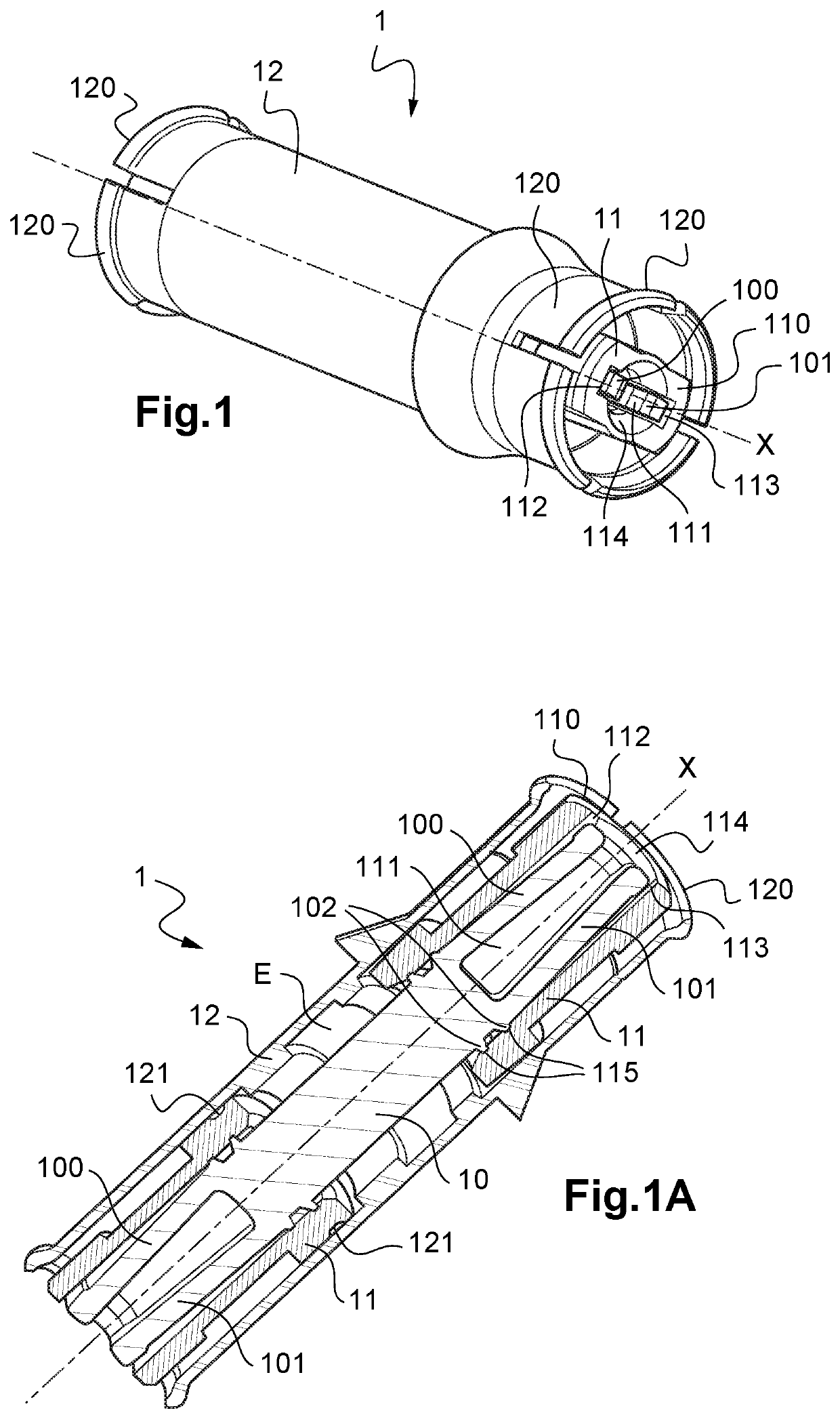
[0057]FIG. 1 is a perspective view of a RF connector according to the invention, forming a coupling connection;
[0058]FIG. 1A is a longitudinal cross-sectional view of the connector according to FIG. 1;
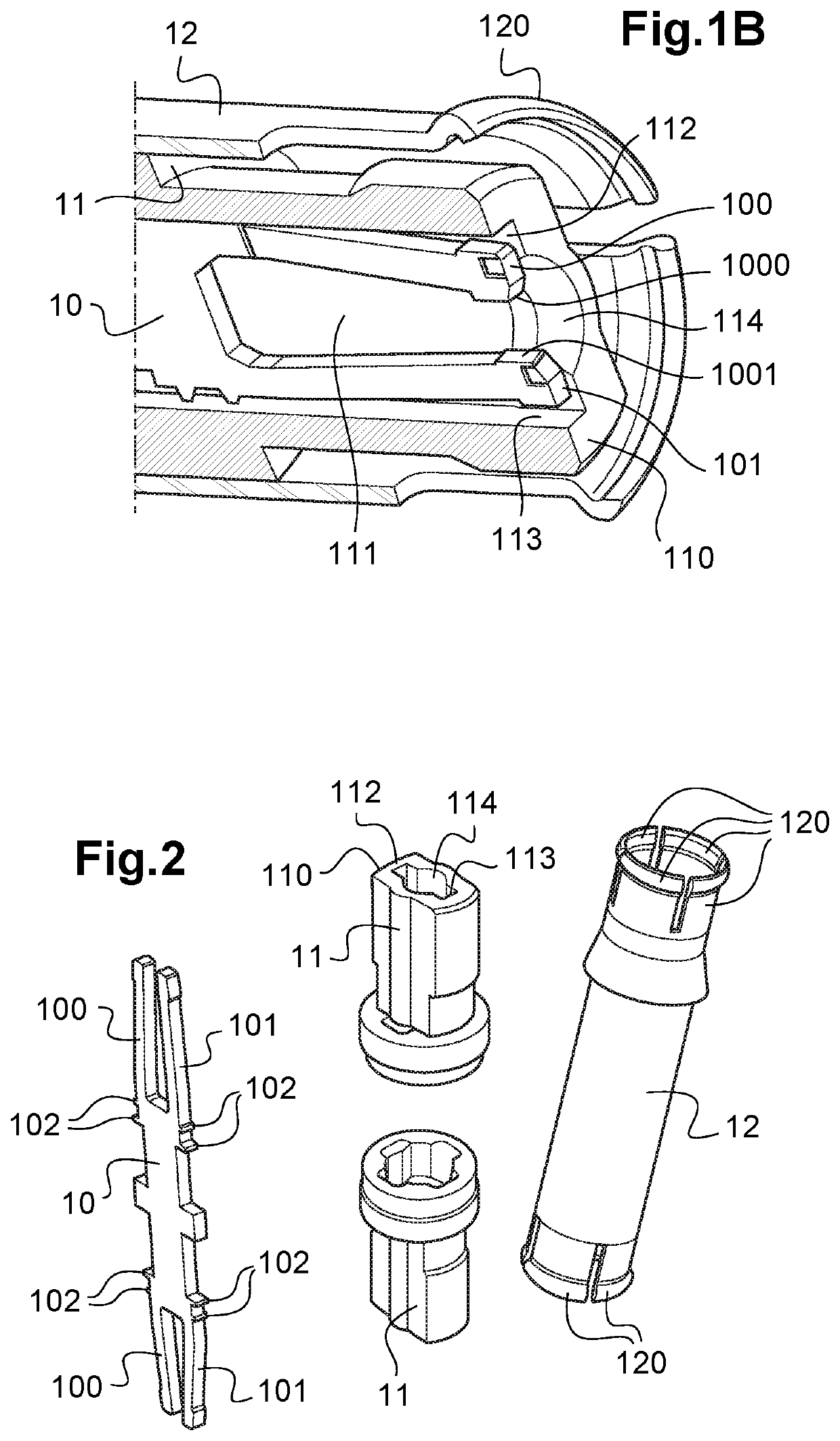
[0059]FIG. 1B is a detail view of one end of the connector according to FIGS. 1 and 1A;
[0060]FIG. 2 shows in perspective views all the components of the RF connector according to FIGS. 1 to 1B;
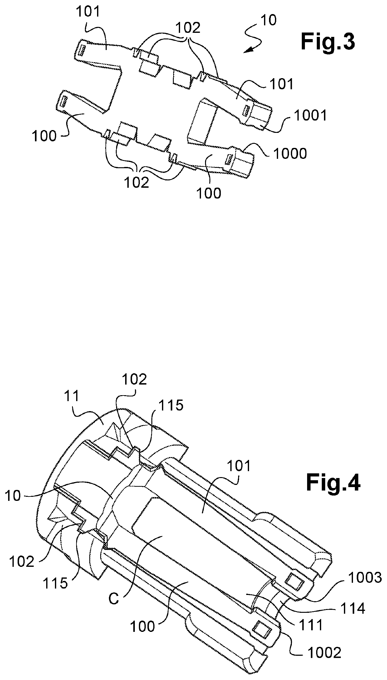
[0061]FIG. 3 is a perspective view of a flat central contact according to the invention;
[0062]FIG. 4 is a longitudinal cross-sectional view of a variant of a connector according to the invention;
[0063]FIG. 5 is a longitudinal cross-sectional view of an exemplary connection assembly, intended to link two printed circuit boards comprising two receptacles joined with a connector forming a connection coupling according to the invention.
[0064]In clarity purposes, the same references designating the same elements of a connector according to the invention are used for all the FIGS. 1 to 4.
[0065]Hereinafter, the invention is described with reference to any type of RF line.
[0066]The RF connector 1 according to the invention is of longitudinal axis X and has a symmetric structure.
[0067]The RF connector 1 comprises, as components, a flat central contact 10, an outer contact 12 forming a body/casing, and two identical electrical insulating solid structures 11 interposed between the flat central contact 10 and the outer contact 12.
[0068]As described below, the flat central contact 10 is mechanically retained by the insulating structures 11 and the shape and the sizing of these components allow them to support any part of the central contact 10, notably to prevent excessive deformation of it.
[0069]The solid insulating structures 11 are mechanically retained into the outer contact 12 and the shape and the sizing of the insulating structures 11 allow them to support any part of the outer contact 10, notably to prevent excessive deformation of it at any direction (radial and circumferential direction).
[0070]The flat central contact 10 has a sheet-like structure, formed by punching to form the desired shape, with the functions of RF signal transmission together with the ground contact through the insulating structures (including air), of conformance to dimensional characteristics requested by the equipment and of conformance to mechanical performances and assembling requests.
[0071]Preferably, the central contact is made of a piece of cut flat metal, preferably made of aged hardened CuBe2.
[0072]More precisely, the central contact 10 is a symmetric structure with each of its two end surfaces shaped as a fork.
[0073]A fork comprises two flexible branches 100, 101 to define inwardly a cavity extending along the axis X. This cavity is intended to receive a contact pin 20; 30 of a complementary connector 2;3.
[0074]The extremities of the two flexible branches 100, 101 of the fork are configured such as to apply a contact force to the contact pin 20; 30, said force being normal to the axis X, as shown by the symbolised arrows on FIG. 5. This contact force shall be maintained whatever the specified maximum angle of swivelling with the counterpart pin 20, 30. This angle may be of the order of some degrees.
[0075]This ensures a good electrical resistance between the central contacts of the connector 1 of the invention and a complementary connector 2, 3 and the good transmission of the RF signals. The shape of the flat central contact 10 is adjusted for the impedance matching at a given frequency range, for example from 0 to 6 GHz.
[0076]Moreover, the middle parts of the branches are designed in order to define a inner cavity C which volume allows the counterpart pin 20, 30, to be tilted with the specified maximum angle.
[0077]Advantageously, in order to increase the contact area or the number of contact points between the flat central contact 10 and a complementary contact pin 20; 30, the inner surface 1000, 1001 of the end of each branch 100, 101 of a fork is a V-shaped groove surface or a circular arc surface (FIG. 3). These surfaces improve the electrical performance, and also improve the alignment of the pin 20; 30 into the flat central contact 10, and give to the complementary contact pin 20, 30 a good position when there is radial misalignment or tilt angle mating.
[0078]In its central portion, the flat central contact 10 has a plurality of outer projections or harpoons 102 which are each mechanically retained into an inner groove 115 of one solid insulating structure 11. These projections or harpoons 102 can apply a retention force with the corresponding inner grooves of the insulator 7. A plurality of harpoons enhance the retention force and at the same time make the flat central contact 10 more stable when this latter is elongated and the force has been apply inwardly along axis when mating.
[0079]In the shown example, each lateral side of the central portion of the central contact 10 has two projections 102 to be retained mechanically into inner grooves 115 (FIGS. 1A, 4). The mechanical interference between the projections 102 and the insulating structure 11 increase the holding force between these two components without increasing the interference mating condition between them. These holding forces allow also the centring of the central contact 10 into the insulating structure 11. The projections 102 are preferably realized by cutting the metal sheet during the stamping of the central contact 10.
[0080]Each insulating structure 11 is an axisymmetric body which closely abuts both the inner surface of the outer contact 12 and the outer surface of the central contact 11.
[0081]According to the invention, a solid insulating structure 11 is configured with an inner hole and inner grooves inside the hole to let the flexible branches 100, 101 to move freely radially and to guide the contact pin 20; 30 while enabling its swivelling when inserted into the cavity defined by the fork.
[0082]In other words, according to the invention, the guiding and centring of the complementary contact pin 20; 30 is ensured exclusively by the solid insulating structure 11.
[0083]More precisely, the solid insulating structure 11 has a substantially cylindrical cavity 111 radially extended by two diametrically opposite slots 112, 113 in each of which one of the two branches 100, 101 of the fork is arranged and free to move up to the bottom of a slot 112, 113 (FIGS. 1, 1A, 1B, 5). The sizing of the slots 112, 113 prevents excessive radial and circumferential deflexion of the branches 100, 101 of the central contact 10. Indeed, in case of important deflexion of one branch 100, 101 when misalignment, the bottom of the corresponding slot 112, 113 serves as an abutment and thus prevents any excessive deformation.
[0084]In order to improve the guiding of the contact pin 20; 30, the solid insulating structure 11 has an inner chamfer 114 between the cylindrical cavity 111 and its end face 110.
[0085]Correspondingly, there is an inner chamfer 1002, 1003 at the end of each of the two branches 100, 101 of the fork 10 (FIG. 4). These chamfers work as lead-in when the contact 10 mates with one of the complementary contact pin 20 or 30.
[0086]FIG. 4 shows also an advantageous general shape of the inward cavity of the fork 10. This cavity C is shaped as a frusto-conical. This allows the swivelling of the pin 20 or 30, when inserted into the cavity. In other words, a frusto-conical shape C guarantees a tilt angle for the pin 20 or 30.
[0087]Preferably, the inner cavity 114 of the insulating structure 11 is also shaped as a frusto-conical, or at least with an inner volume to allow the free displacement of the branches of the fork, in order to let it possible the swiveling of the pin 20 or 30.
[0088]Thus, the diameter of the insulator inner hole at end of connector side is a little smaller than at the connector inward side. The width of the cavity C at the end is smaller than the width at the bottom. The width of the cavity at the end is smaller than the diameter of complementary contact pin 20; 30 while the width of the cavity at the bottom is bigger than the diameter of complementary contact pin 20 or 30.
[0089]This smaller hole longitudinal segment in insulator 11 guarantees the good positioning of the complementary contact pin 20 or 30. These two stepped holes are coaxial. The bigger hole longitudinal segment in the insulator 11 and the bigger width at the cavity bottom on flat central contact 10 allow to the complementary contact pin 20 or 30 to swivel when inserted into the cavity defined by the fork 10.
[0090]In the direction perpendicular to flat surface of flat central contact 10, there is no metal material at the cavity longitudinal segment. It means that the swivelling angle along this direction can be much bigger than a usual cylinder female socket which is manufactured by machining process.
[0091]The thickness at the section view of inner grooves in insulator 11 at end of connector side is bigger than that at connector inward side. These two stepped grooves have same axis. The narrow grooves in insulator 11 is suitable to the thickness of the flat central contact 10 and can hold the flat central contact 10 in it. The narrow grooves in insulator 11 will guide and locate the flat central contact 10 to guarantee a gap between the insulator 11 at wider inner grooves area and the flat central contact 10 at the flexible branches 100, 101 area. The gap will allow to the flexible branches 100, 101 to move freely radially during mating and un-mating with the complementary contact pin 20 or 30.
[0092]The inner grooves of the insulator 11 can have several segments of different width. The first segment at the connector inward side is wider than other segments. It can have clearance mating condition with the harpoon 102 on the flat central contact 10. The purpose of these segments of grooves of different widths is for the pre-assembly. Indeed, the pre-assembly may be done manually.
[0093]One the pre-assembly has been achieved, a machine may be embodied to further assembly the flat central contact 10 into the insulator 11. This machine can apply a bigger force than manually in order to obtain an interference mating condition between the other segment of grooves 115 in the insulator 11 and the harpoon 102 on flat central contact 10 to obtain a good retention force.
[0094]Preferably, a fork of a central contact 10 and the corresponding solid insulating structure 11 are arranged such that the end of the branches 100, 101 are located in the same plane of the end face 110 of the solid insulating structure 11 (FIGS. 1, 1A, 1B, 4).
[0095]The outer contact 12 supports and protects the insulating structures 11. To ensure the electrical contact at the ends of the outer contact 12, this latter is slotted at its ends defining contact petals 120. The petals 120 may be thicker than the thickness of the rest of the contact 12. Due to this increase of the thickness, the electrical resistance is reduced and the mechanical resistance is stronger.
[0096]To retain the solid insulating structures 11 into the outer contact 12, punches 121 may be realized.
[0097]As shown on FIGS. 1A and 5, it may be provided a space E filled with air, and hence without solid insulating structure, between the outer contact 12 and the central contact 10, in the central portion of the connector 1. This conception allows to have different lengths of connectors 1 by using same solid insulating structures 11, while preserving an adapted characteristic impedance all along the connector 1. In another embodiment, especially for short connector; the insulator structure may be constituted of the half parts sandwiching the central contact along the connection axis.
[0098]The connector 1 which has been described is advantageously used as a connection coupling 1 into a connection assembly or module 4 used to link two parallel printed circuit boards, i.e. into a board-to-board connecting system 4.
[0099]FIG. 5 shows the connection coupling 1, usually called bullet, according to the invention, the first receptacle 2 and the second receptacle 3 and of the connection assembly 4.
[0100]The first receptacle 2 is intended to be brazed or welded to a first printed circuit board. The first receptacle 2 of longitudinal axis X2 comprises a contact pin 20, a rigid body 21 with a recess, and a plurality of peripheral contacts 22 maintained into the rigid body 21 and arranged at the periphery of the contact pin 20.
[0101]The plurality of peripheral contacts 22 forms a ground contact.
[0102]An insulator 23 is positioned between the contact pin 20 and the ground contact 22.
[0103]The recess of the body 21 houses the contact pin 20, the ground contact 22 and the insulator 23.
[0104]The second receptacle 3 intended to be brazed or welded to a second printed circuit board. The second receptacle 3 of longitudinal axis X3 comprises a contact pin 30, a rigid body 31 with a recess, and a plurality of peripheral contacts 32 maintained into the rigid body 31 and arranged at the periphery of the contact pin 30.
[0105]The plurality of peripheral contacts 22 forms a ground contact.
[0106]An insulator 33 is positioned between the contact pin 30 and the ground contact 32.
[0107]The recess of the body 31 houses the contact pin 30, the ground contact 32 and the insulator 33.
[0108]The body 31 of second receptacle 3 is also a centring end piece comprising a centring surface 34. As illustrated in FIG. 5, the centring surface 34 is of annular shape and of circular section.
[0109]When the connection coupling 1 is connected to the first receptacle 2 and to the second receptacle 3, as illustrated in FIG. 5, the branches 100, 101 of each end of the central contact 12 are in forced contact respectively with the contact pins 20, 30 and the elastic ground contacts 22, 42 bear against the petals 120 of the connection coupling 1. The centring surface 34 of the second socket 34 cooperates with the elongate rigid outer contact 12 of the coupling 1 defining a sliding link.
[0110]In an advantageous embodiment, one of the end surfaces of the connection coupling 1 can be fixed in the first receptacle 2, notably by clipping the end of the outer contact 12 into the body 21, whereas the other end can be floating mounted in the second receptacle 3.
[0111]Even if the illustrated embodiment of FIG. 5 shows that the different axis X, X2 and X3 of the different components are aligned, the connection coupling 1 according to the invention allows significant radial misalignment of the connection assembly because the contact pins 20, 30 in contact with the branches 100, 101 of the flat central contact 1 are sufficiently free to move radially into the cavity 111 and the petals 120 of the outer contact 12 have a high degree of elasticity.
[0112]A significant axial tolerance of the connection assembly according to the invention can be obtained by virtue of the sliding link on the side of the second receptacle 3. This/these axial and/or radial misalignment(s) allow(s) a tolerance on the distance between the two elements to be connected by the connection assembly according to the invention, such as printed circuit boards PCB.
[0113]Other variants and enhancements can be provided without in any way departing from the framework of the invention.
[0114]If all the shown examples are about a connector serving as a connection coupling with a symmetric structure and both ends shaped as a fork which branches are free to move into a solid insulating structure, the invention concerns also a connector with only one end shaped as a fork with two branches and only one solid insulating structure.
[0115]Also, the invention applies to any connector with or without the presence of an outer contact.
[0116]The expression “comprising a” should be understood to be synonymous with “comprising at least one”, unless otherwise specified.

PUM

no PUM

Description & Claims & Application Information

We can also present the details of the Description, Claims and Application information to help users get a comprehensive understanding of the technical details of the patent, such as background art, summary of invention, brief description of drawings, description of embodiments, and other original content. On the other hand, users can also determine the specific scope of protection of the technology through the list of claims; as well as understand the changes in the life cycle of the technology with the presentation of the patent timeline. Login to view more.

Similar technology patents

Disposable spoon

Owner:CHAO CHAO HUI

Classification and recommendation of technical efficacy words

Why Eureka
Try Eureka