Device and method for reducing wind resistance power of large geotechnical centrifuge

a geotechnical centrifuge and wind resistance power technology, which is applied in the direction of centrifuges, structural/machine measurement, instruments, etc., can solve the problems of all instruments in the centrifuge chamber, the heat dissipation requirements of high-acceleration centrifuges cannot be met, and the wind resistance power and corresponding energy consumption are reduced, and the sealing requirements are lower.

Pending Publication Date: 2021-12-30
ZHEJIANG UNIV
View PDF2 Cites 1 Cited by
  • Summary
  • Abstract
  • Description
  • Claims
  • Application Information

AI Technical Summary

Benefits of technology

[0030]1) The helium gas is used to replace the air in the closed centrifuge chamber of the large geotechnical centrifuge (according to the present invention, helium gas is used for replacement, but other injected gases can also be used). Because the density drops by 86%, the wind resistance power of the geotechnical centrifuge under the same working conditions and normal pressure can be reduced by 86%, which greatly reduces the wind resistance power and corresponding energy consumption. There is no such report at domestic nor abroad.
[0031]2) Compared with vacuuming to reduce the wind resistance power, the present invention does not require vacuuming, so the centrifuge chamber structure is simpler, and sealing requirements are lower. Large bearings will not leak oil due to vacuuming, and no huge energy-consuming vacuum system is required. The construction cost is greatly reduced, meanwhile the energy consumption required for vacuuming is no longer needed. As a result, operating cost is lowered and reliability is increased.
[0032]3) Heat dissipation equipment is arranged inside a vacuum chamber, and a helium gas circulation cooling wind duct is also provided, which can further improve heat exchange coefficient and increase heat dissipation effect. A huge wind pressure difference in the large geotechnical centrifuge is used to guide the high-temperature helium gas in the high wind pressure area into the semicircular tube cylindrical cooling device and a semicircular tube side of a top cooler. After heat exchange, the helium gas is sent to a central low-pressure area by a pressure difference, which takes full advantage of a cooling capacity of a cooling medium and greatly improves heat exchange efficiency.
[0033]4) Different from a cantilever beam rotor of a single-bearing system used in the conventional geotechnical centrifuge, the high-speed rotor of the present invention is provided with the top bearing system, which greatly increases the rigidity and operating stability of the high-speed rotor and solves the problem of vibration of the high-speed rotor.
[0034]5) The special vibration isolation gasket is used, in such a manner that the vibration transmitted to the top bearing system support device by the main shaft is separated from the centrifuge chamber, thereby avoiding resonance of the centrifuge chamber and the main shaft, and ensuring safety of the centrifuge chamber.
[0035]Therefore, the present invention is more economical when operating at an acceleration of below 1500 g, and can maintain the temperature below 45° C.

Problems solved by technology

Such a huge heat exchange requires huge air volume, but excessive wind will affect the vibration of the rotating arm.
As a result, conventional air-cooling can no longer meet the heat dissipation requirements of high-acceleration centrifuge.
Without sufficient temperature control, all instruments in the centrifuge chamber will have problems.
At this time, even the combination of the air-cooling and the water-cooling cannot satisfy the heat dissipation requirements.
However, vacuuming will cause other problems.
First, air molecules are thin under vacuum, the heat transfer ability is also greatly reduced, and air convection is impossible under vacuum.
As a result, the heat of the rotating arm caused by the friction between the rotating arm and the air cannot be effectively transferred.
Second, bearings of the centrifuge will leak oil under high vacuum, and sealing around the centrifuge chamber becomes difficult, so the vacuum cannot be too high.
Third, the vacuum also greatly increases the cost of the centrifuge chamber.

Method used


Image

  • Device and method for reducing wind resistance power of large geotechnical centrifuge
  • Device and method for reducing wind resistance power of large geotechnical centrifuge
  • Device and method for reducing wind resistance power of large geotechnical centrifuge

Examples


Embodiment Construction

[0045]Referring to the drawings, the present invention will be further illustrated.

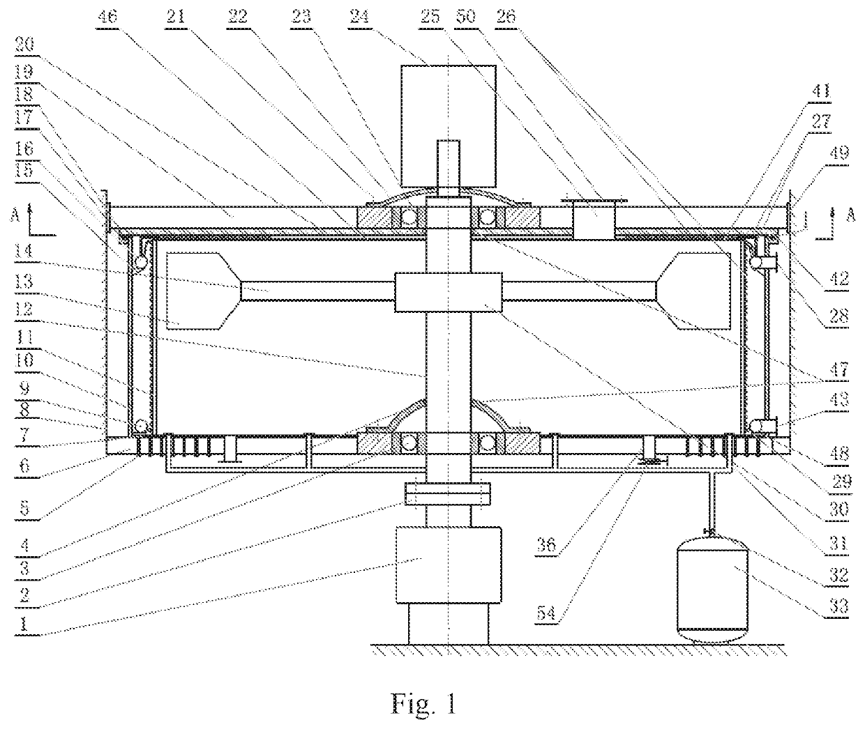
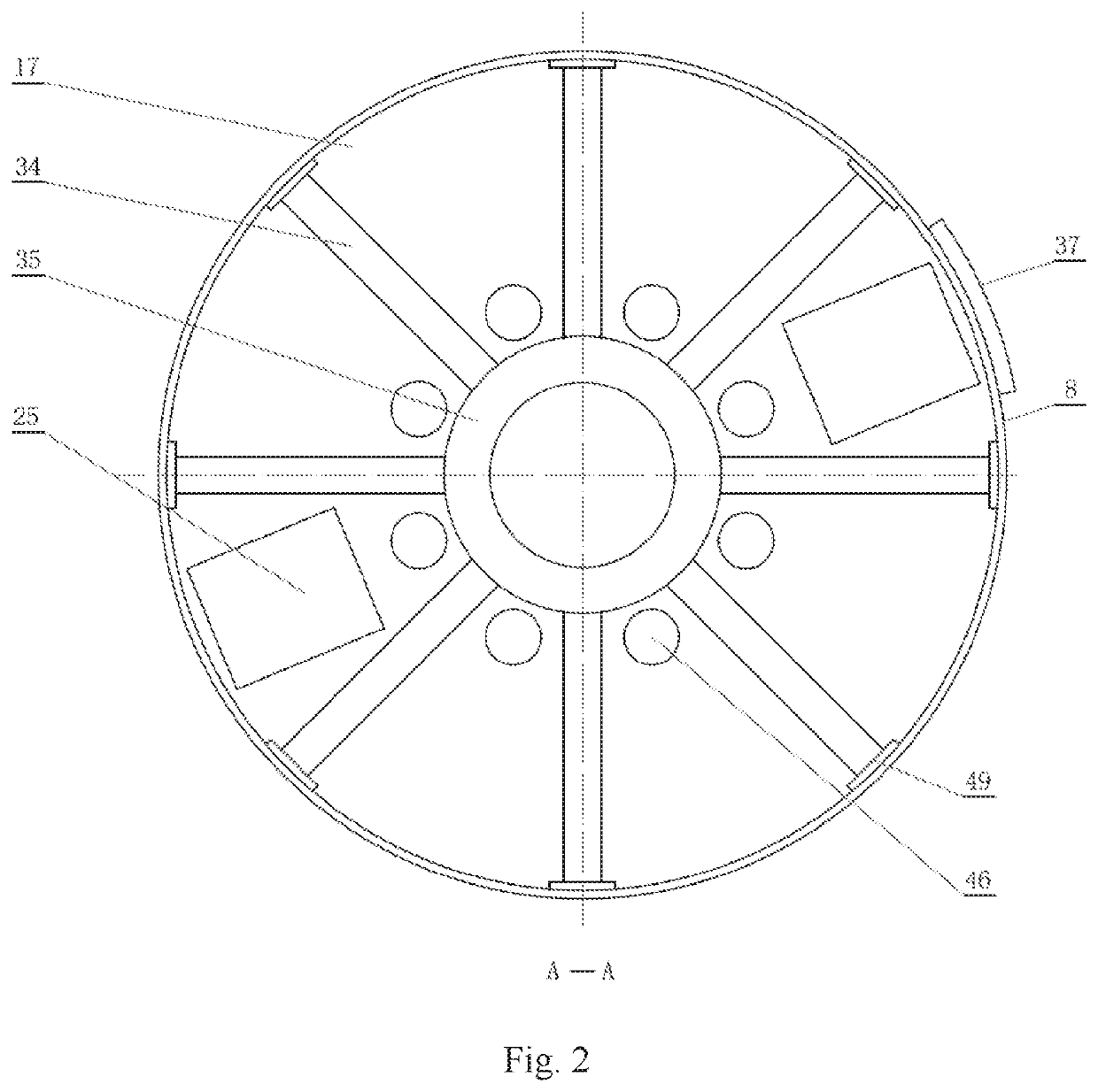
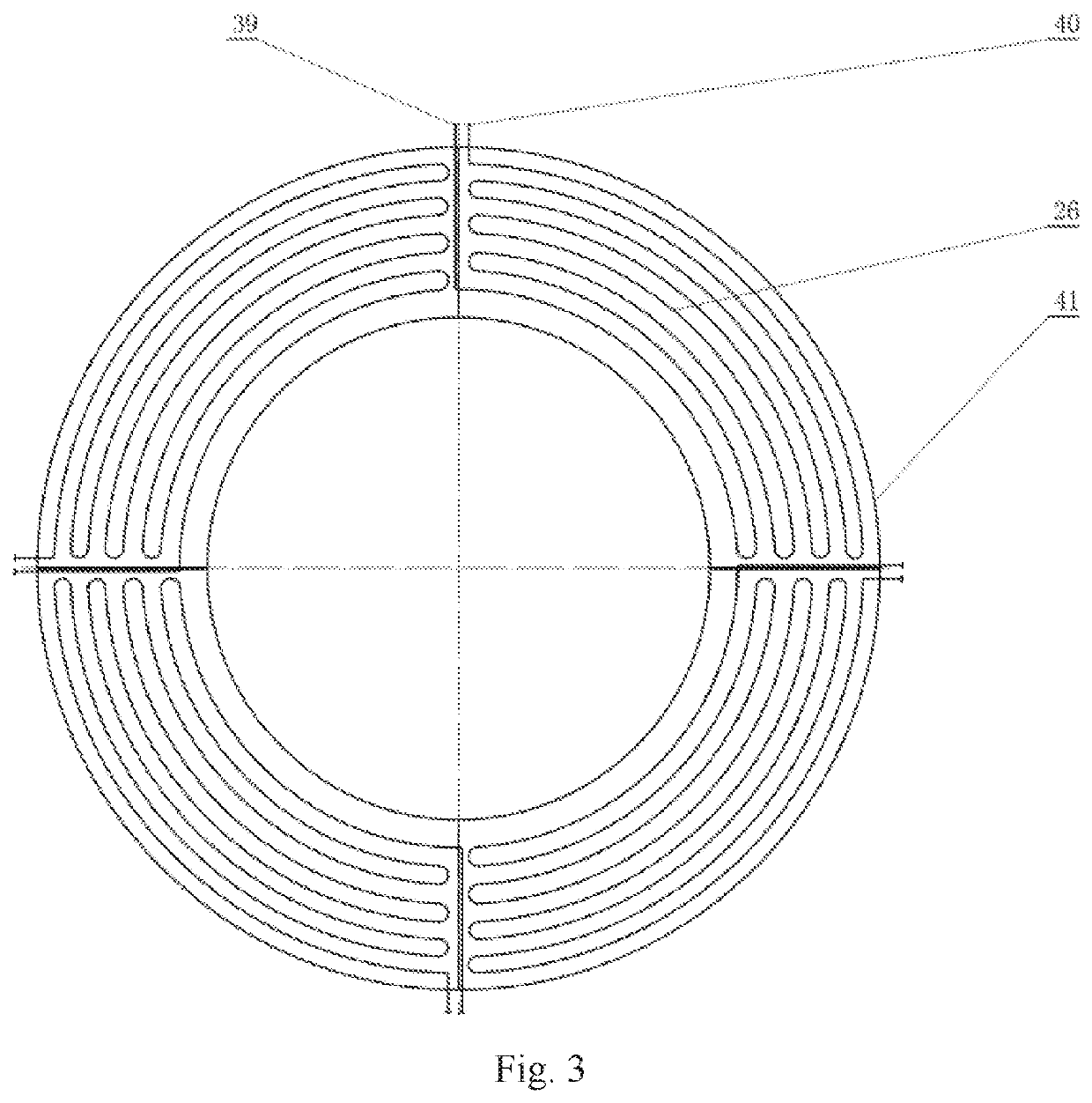
[0046]Referring to FIGS. 1 and 2, the present invention comprises a cylindrical shell 10, a top sealing plate 20 whose bottom is equipped with a top semicircular tube cooling plate 41, a bottom sealing plate 7, and a vibration isolation gasket 18, which all together form a sealed centrifuge chamber

[0047]A high-speed rotor system 30 is enclosed in the centrifuge chamber; a semicircular tube cylindrical cooling device 11 is installed between an internal side of the cylindrical shell 10 and the high-speed rotor system 30; a lower end of a main shaft 12 of the high-speed rotor system 30 extends out of the bottom sealing plate 7 after passing through a bottom bearing sealing cover 4 and a bottom bearing system 3, and then is sequentially connected to a coupling 2 and a motor 1; the main shaft 12 and the bottom bearing sealing cover 4 are sealed by a main shaft dynamic seal; a top end of the main shaft 12 o...


PUM


Abstract

A device and a method for reducing wind resistance power of a large geotechnical centrifuge are provided. A semicircular tube cylindrical cooling device is installed between an internal side of a high-speed rotor system and a cylindrical shell. A serpentine top semicircular tube cooling plate is provided right above a hanging basket, and return helium gas inlet holes are opened at a center of the top semicircular tube cooling plate. A helium gas in a helium gas storage tank passes through helium gas outlets on the helium gas inlet pipes, and enters a centrifuge chamber from a bottom sealing plate. The helium gas is used to replace air in the centrifuge chamber to reduce the wind resistance power and corresponding energy consumption. No vacuuming is required, so sealing requirements are lower. Heat dissipation equipment is placed inside the centrifuge chamber, and a helium gas circulation wind duct is added to improve heat exchange coefficient and heat dissipation effect. A special vibration isolation gasket is used, in such a manner that the vibration transmitted to the top bearing system support device by the main shaft is separated from the centrifuge chamber, thereby avoiding resonance of the centrifuge chamber and the main shaft, and ensuring safety of the centrifuge chamber. The present invention is more economical when operating at an acceleration of below 1500 g, and can maintain the temperature below 45° C.

Description

BACKGROUND OF THE PRESENT INVENTIONField of Invention[0001]The present invention relates to a centrifuge technology for reducing wind resistance power, and more particularly to a device and a method for reducing wind resistance power of a large geotechnical centrifuge.Description of Related Arts[0002]Geotechnical centrifuge with large-diameter, high-acceleration, and hyper gravity is an indispensable device for reproduction test of geological evolution process such as geotechnical evolution, geological structure evolution, and geological disaster reduction. As the acceleration g continues to increase, the wind resistance power of the centrifuge also increases sharply. According to the conventional method is all over the world for estimating wind resistance power, the wind resistance power formula is Nw=ρA1ω3B1, wherein A1 and B1 are coefficients related to shape and geometric size, respectively. The power Nw is proportional to air density p as well as to rotating speed ω3 of a high-...

Claims


Application Information

Patent Timeline
Patent Type & Authority Applications(United States)
IPC IPC(8): B04B15/02B04B15/08B04B3/00B04B7/06B04B7/08
CPCB04B15/02B04B15/08B04B7/08B04B7/06B04B3/00B04B7/00G01M99/008
Inventor ZHENG, CHUANXIANGWEI, SHUANGZHOU, HAIFENG
Owner ZHEJIANG UNIV
Why Eureka
Try Eureka