
Nanofiber reinforcement of attached hydrogels

a hydrogel and nanofiber technology, applied in the direction of prosthesis, coating, surgery, etc., can solve the problems of poor adhesion and concentration of stress at the hydrogel-substrat interface, weak shear strength than the bone-cartilage interface, and cyanoacrylate can have cytotoxic effects,

Active Publication Date: 2022-01-06
DUKE UNIV
View PDF0 Cites 3 Cited by
  • Summary
  • Abstract
  • Description
  • Claims
  • Application Information

AI Technical Summary

Benefits of technology

The patent describes a new method for attaching a hydrogel to an implant, which involves securing a nanofibrous network to the implant before infiltrating the hydrogel into the network. This new method creates an implant that can mimic the strength of cartilage and has better adhesion to the substrate. The nanofibrous network is secured to the implant with a strong cement, and the hydrogel is impregnated into the network. The resulting implant has a shear strength that is greater than previous methods, making it more robust. The new method also allows for the formation of a multiple-network hydrogel, which further strengthens the attachment. Overall, this new method creates an implant that can better mimic the natural environment and withstand higher loads.

Problems solved by technology

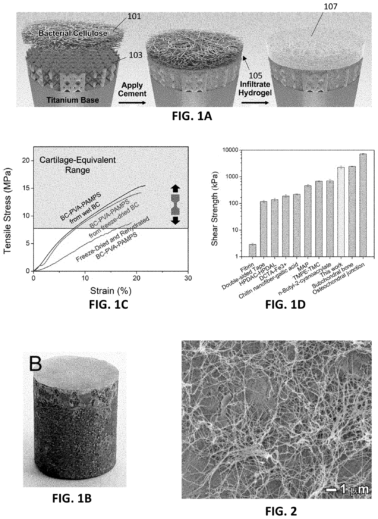
Although it would be beneficial for hydrogels to be attached to bone or to a porous substrate that integrates with bone with a shear strength similar to the shear strength of the osteochondral junction (e.g., 7.25 MPa), or at least the shear strength of subchondral bone (e.g., 2.45 MPa), current strategies for attaching hydrogels to a substrate result in shear strengths weaker than the bone-cartilage interface.
In addition to being too weak, cyanoacrylate can have cytotoxic effects due to the breakdown of cyanoacrylates into formaldehyde.
One inherent problem with previous attachment strategies is that they seek adhesion to the hydrogel in the wet state, wherein water will inherently interfere in the attachment between the macromolecular component of the hydrogel and the substrate.
A second problem with many of these strategies is that the adhesive cannot penetrate and interdigitate with the hydrogel, resulting in poor adhesion and concentration of stress at the hydrogel-substrate interface.

Method used


Image

  • Nanofiber reinforcement of attached hydrogels
  • Nanofiber reinforcement of attached hydrogels
  • Nanofiber reinforcement of attached hydrogels

Examples


examples

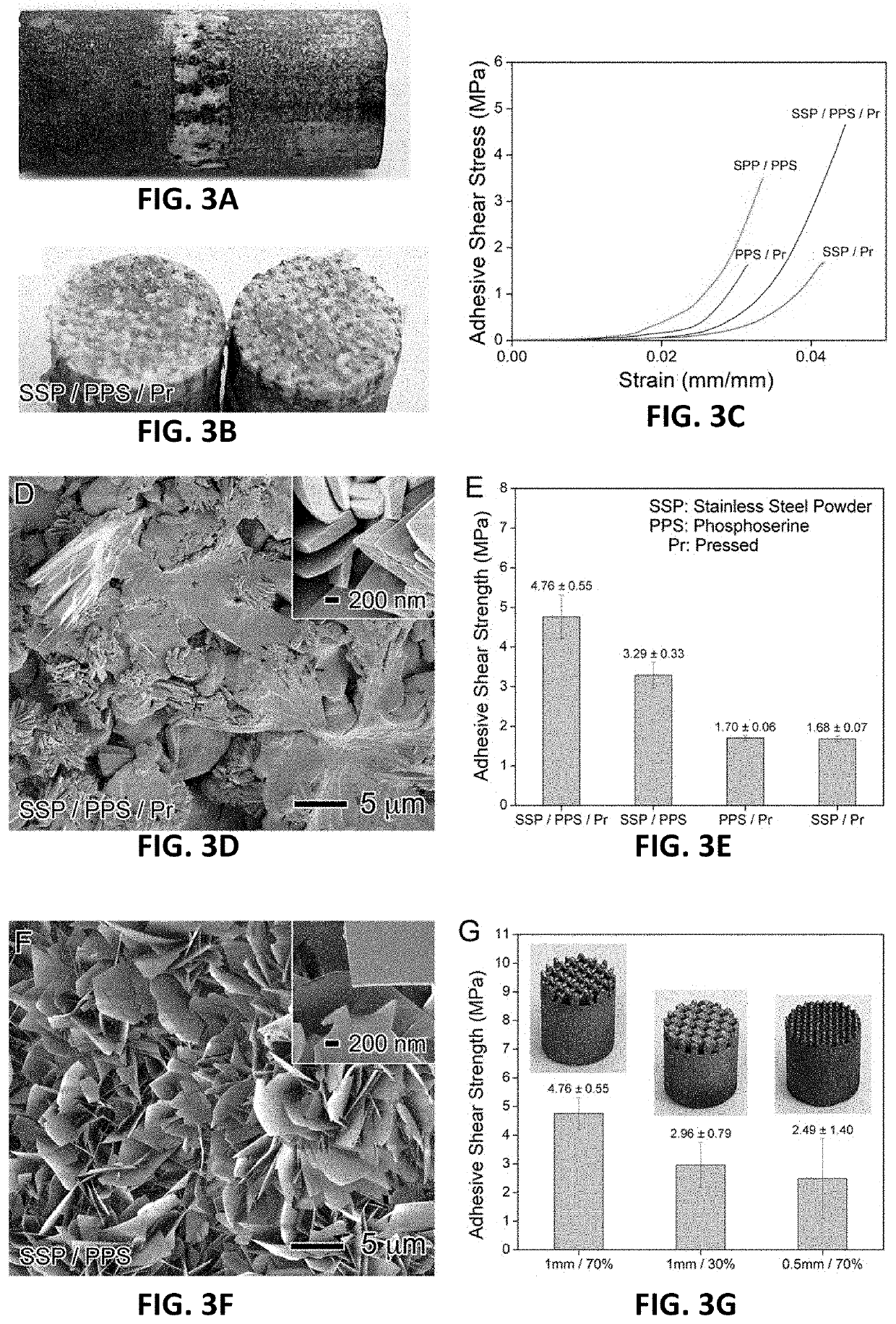
[0133]A hydrogel may be attached to a titanium base with the strength and fatigue of cartilage on bone. Current strategies for attachment of a hydrogel to a substrate are weaker than the osteochondral junction by a factor of ten. The methods and apparatuses described herein may achieve an attachment strength between a hydrogel and a porous substrate equivalent to the osteochondral junction. Thus a hydrogel may be attached to a titanium base with the shear strength and fatigue strength of the osteochondral junction.

[0134]A hydrogel-capped implant may be configured so as to promote osseointegration while minimizing abnormal stresses that might arise due to slight imperfections in the placement of the implant during surgery. The hydrogel may be attached to a porous titanium base with the strength of the osteochondral junction. These methods and apparatuses may allow fabrication of a hydrogel-capped implant for implantation, enabling hydrogel-capped implants for rapid repair of cartilag...


PUM

PropertyMeasurementUnit
Fractionaaaaaaaaaa
Pressureaaaaaaaaaa
Lengthaaaaaaaaaa

Abstract

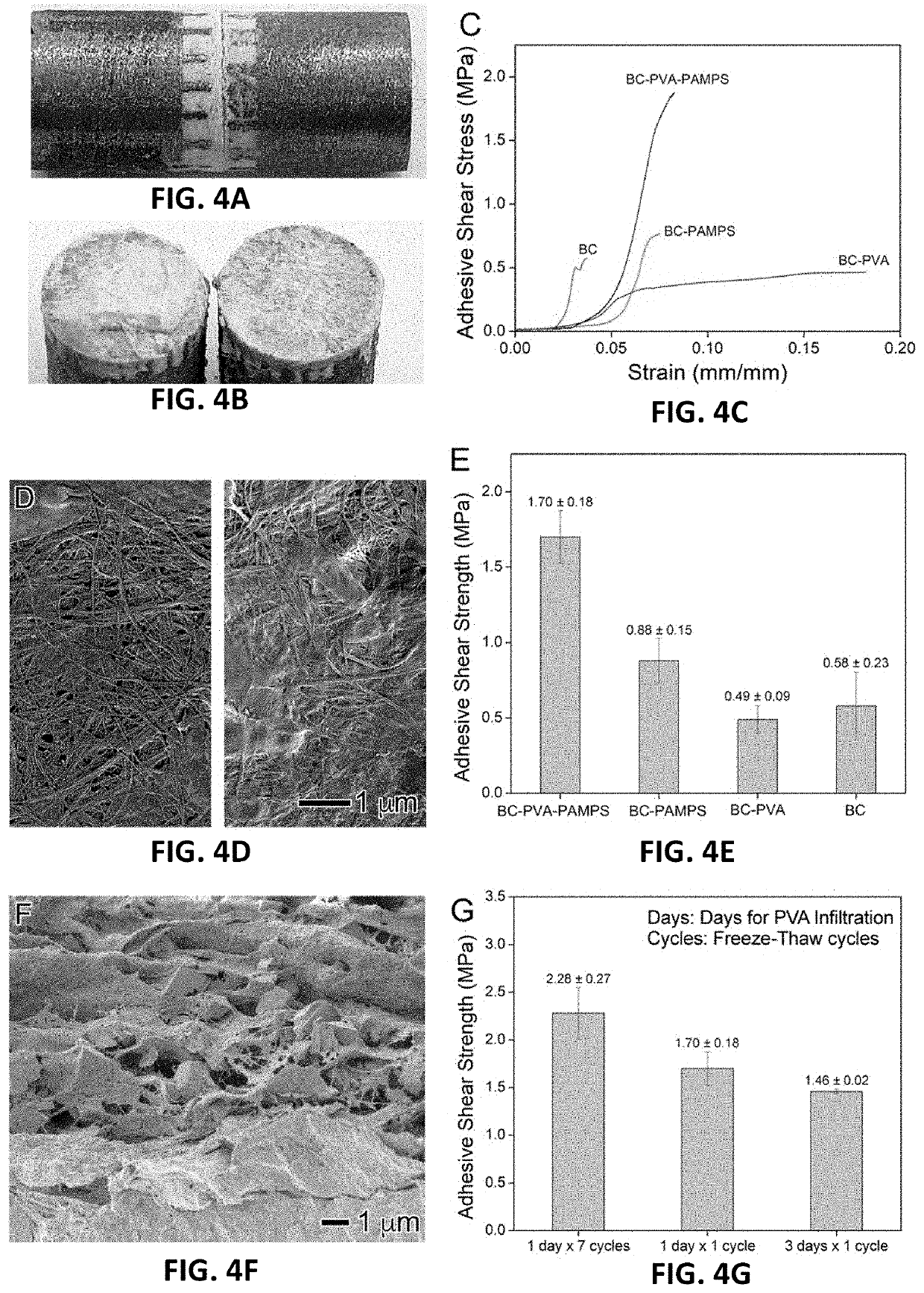
Described herein are hydrogels attached to a base with the strength and fatigue comparable to that of cartilage on bone and methods of forming them. The methods and apparatuses described herein may achieve an attachment strength between a hydrogel and a substrate equivalent to the osteochondral junction. In some examples the hydrogel may be a triple-network hydrogel (such as BC-PVA-PAMPS) that is attached to a porous substrate (e.g., a titanium base) with the shear strength and fatigue strength equivalent to that of the osteochondral junction.

Description

CROSS REFERENCE TO RELATED APPLICATIONS[0001]This patent application claims priority to U.S. provisional patent application no. 63 / 046,944, titled “NANOFIBER REINFORCEMENT OF ATTACHED HYDROGELS,” filed on Jul. 1, 2020, and U.S. provisional patent application No. 63 / 183,670, titled “HYDROGEL-COATED ORTHOPEDIC IMPLANTS,” and filed on May 4, 2021, each of which are herein incorporated by reference in its entirety.INCORPORATION BY REFERENCE[0002]All publications and patent applications mentioned in this specification are herein incorporated by reference in their entirety to the same extent as if each individual publication or patent application was specifically and individually indicated to be incorporated by reference.FIELD[0003]This disclosure relates generally to artificial cartilage materials in implants suitable for repair of cartilage, including specifically methods and compositions for attaching a polymer network hydrogel material to a surface of an implant, as well as implants i...

Claims


Application Information

Patent Timeline
IPC IPC(8): A61L27/52A61L27/20A61L24/02A61L27/34A61L27/30A61L27/32A61L27/36
CPCA61L27/52A61L27/20A61L24/02A61L27/34A61L2400/12A61L27/32A61L27/3608A61L2430/06A61L2430/02A61L27/306A61L27/06A61L27/50A61L27/56C08L29/04C08L1/02C08L33/24A61L27/48
Inventor WILEY, BENJAMIN J.TONG, HUAYUZHAO, JIACHENG
Owner DUKE UNIV
Learn More