
Building drainage stack, forming mould thereof and forming method thereof

a technology of building drainage and forming moulds, which is applied in the field of civil engineering, can solve the problems of limited improvement of the drainage capacity of plastic pipes, the damage to the water seals of floor drains, and the stink of toilets, and achieve the effects of reducing the pressure fluctuation of the building drainage stack, reducing the water velocity of falling water, and large leaving curvatur

Active Publication Date: 2022-01-06
YUZHOU JIETONG PLASTIC CO LTD
View PDF0 Cites 0 Cited by
  • Summary
  • Abstract
  • Description
  • Claims
  • Application Information

AI Technical Summary

Benefits of technology

The invention provides a building drainage stack with a reduced pressure fluctuation and lowered falling water velocity. This is achieved by arranging a helical inner rib on the inner wall of the drainage stack and designing a helical blade with rounded corners to avoid stress concentration. The helical blade has a first curve, a second curve, and a third curve to eliminate sharpness and improve the water flow wall-attached effect. The forming mold and method of the invention are simple, cost-effective, and require minimal processing space and investment.

Problems solved by technology

In the water flow status, water flows are less influenced by pipe wall frictional resistance, descend quickly, and form accelerative flows under the gravitational action, thereby giving rise to violent pressure fluctuation and large flow noise which can easily cause damage to water seals of floor drains and stink phenomena in toilets.
The improvement on the drainage capacity of the plastic pipes is limited by disadvantages of relatively high pressure fluctuation in the pipes and stink phenomena in the toilets.

Method used


Image

  • Building drainage stack, forming mould thereof and forming method thereof
  • Building drainage stack, forming mould thereof and forming method thereof
  • Building drainage stack, forming mould thereof and forming method thereof

Examples


embodiment 1

t of a Building Drainage Stack

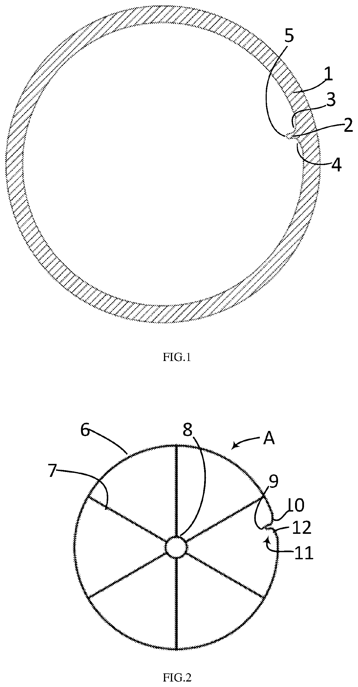
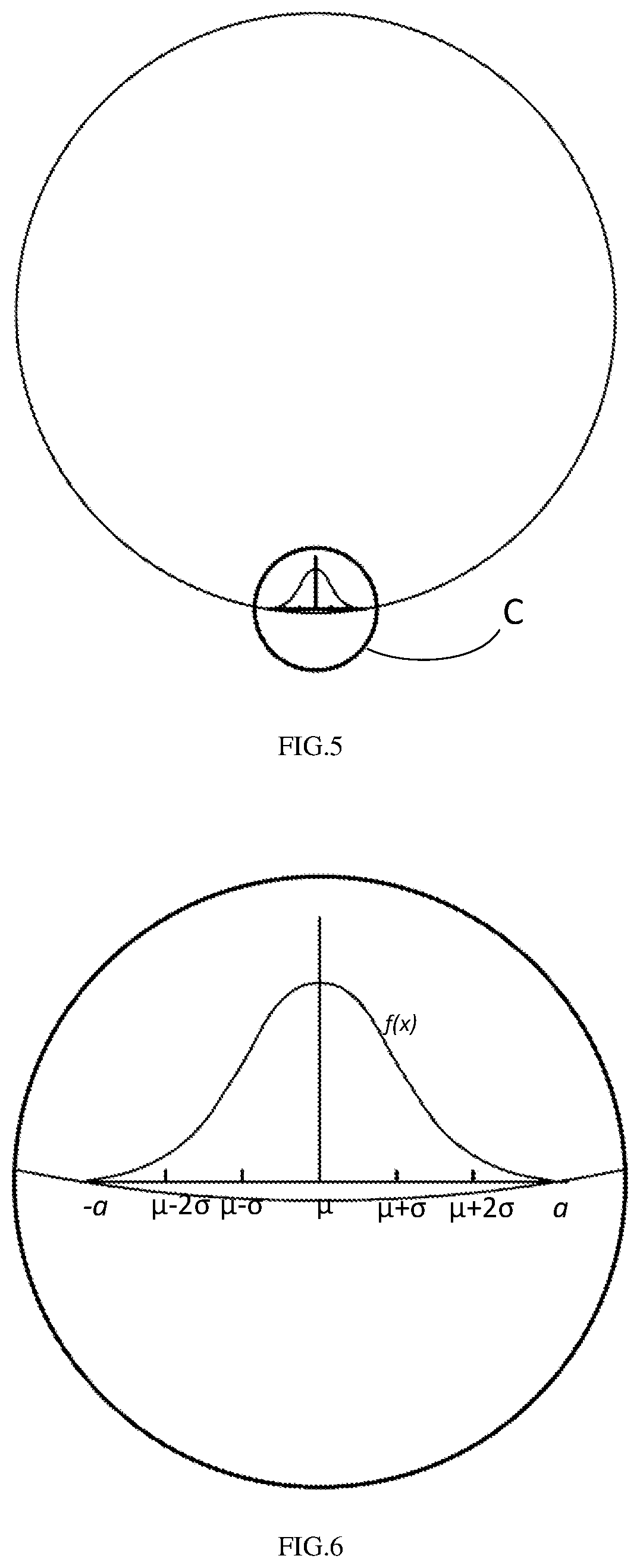
[0047]With reference to FIG. 1, the embodiment of the invention provides a building drainage stack comprising a stack body (1) and at least one helical blade (2). The helical blade (2) tends helically as a whole in the axial direction of an inner wall of the stack body (1), and the helical blade (2) is fixedly connected with the inner wall of the stack body (1) through a bottom side thereof. The inner side of the radial cross section of the helical blade (2) is presented as a first normal distribution curve, the abscissa axis of the first normal distribution curve is on a chord of the inner wall of the stack body (1), and the distance from the chord to the center of the stack body (1) is greater than the half of the inner diameter of the stack body (1) but less than the inner diameter of the stack body (1). In the embodiment, the normal distribution curve at least comprises three curves. In the embodiment, curves are non-straight lines, and non-straight...

embodiment 2

t of a Forming Mould of a Building Drainage Stack

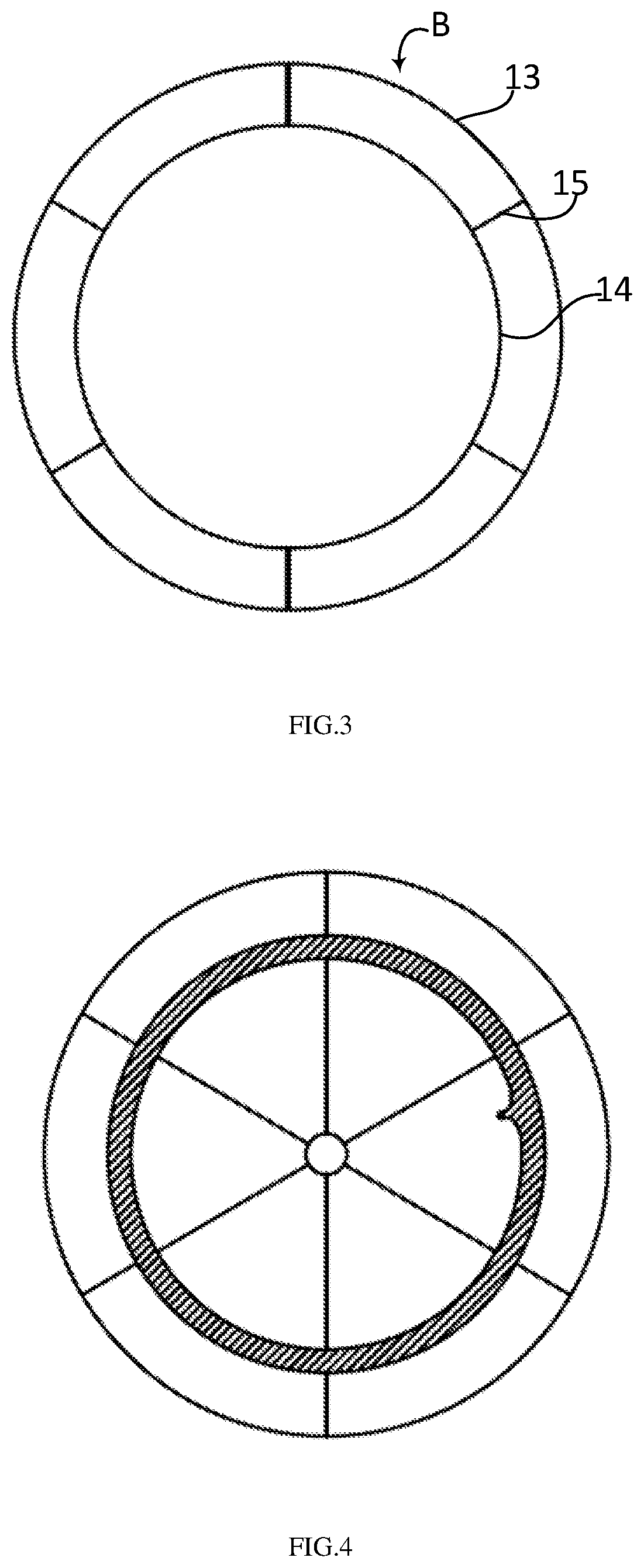
[0050]With reference to FIG. 2-FIG. 4, a forming mould of a building drainage stack provided by the embodiment 2 of the invention comprises a stack inner wall forming mould (A) and a stack outer wall forming mould (B). The stack inner wall forming mould (A) is used for forming an inner wall of the building drainage stack by extrusion moulding or cutting; the stack outer wall forming mould (B) is used for forming an outer wall of the building drainage stack by extrusion moulding or cutting.

[0051]In this case, the forming mould of the building drainage stack provided by the embodiment 2 of the invention has the advantages of convenience for moulding, simple materials and low cost.

[0052]The stack inner wall forming mould (A) comprises an axle sleeve (8), a plurality of first support spokes (7) and an inner wall moulding template body (6). one end of each of the plurality of first support spokes (7) is fixedly connected with an outer wall...

embodiment 3

t of a Forming Method of a Building Drainage Stack

[0057]The forming method of the building drainage stack provided by the embodiment of the invention comprises the following steps:

[0058]S1: firstly, using the outer wall forming mould (B) provided by the embodiment of the invention to perform first cutting or extrusion moulding on a to-be-formed material, so as to obtain a cylinder with the diameter equal to the outer diameter of the stack body (1);

[0059]S2: fixing the cylinder;

[0060]S3: punching an axial center of the cylinder to form a through hole, and obtaining an intermediate product with the diameter larger than or equal to the outer diameter of the axle sleeve (8) of the inner wall forming mould provided by the embodiment 2 of the invention and less than twice the distance from the vertex of the inner bulge (11) to the axis of the cylinder;

[0061]S4: configuring an output shaft of the rotating motor to penetrating into the through hole from one end of the through hole to the ot...


PUM

PropertyMeasurementUnit
inner diameteraaaaaaaaaa
distanceaaaaaaaaaa
diameteraaaaaaaaaa

Abstract

The invention discloses a building drainage riser, its forming mold and forming method. The riser comprises a riser body and at least one spiral blade. The spiral blade is in a spiral direction on the inner wall of the riser body, and the spiral blade is fixedly connected to the inner wall of the riser body through its bottom side; the inner side of the radial section of the spiral blade presents the first normal distribution curve and the first normal distribution The abscissa axis of the curve is located on a chord of the inner wall of the riser body, and the distance from the chord to the center of the riser body is greater than half of the inner diameter of the riser body and less than the inner diameter of the riser body. The inner wall of the building drainage riser is provided with a spiral inner reinforcement with a radial section inside the first normal distribution curve, which completely eliminates the sharp tip and the sharp joint between the top and the inner wall of the building drainage riser, reduces the pressure fluctuation in the pipe during drainage and reduces the falling water flow speed. In addition, the molding die and forming method have the advantages of simple structure and low cost.

Description

TECHNICAL FIELD[0001]The invention relates to the technical field of civil engineering, in particular to a building drainage stack, a forming mould thereof and a forming method thereof.BACKGROUND OF THE INVENTION[0002]As frequently-used pipes for building drainage, plastic pipes with smooth inner walls have low frictional resistance, and easily cause water plug flows in case of relatively high water velocity and relatively high flow when used for a building drainage stack, wherein, when the building drainage stack is used for gravity drainage, the water plug flows are mass plug water flows falling down in pipes, which are formed by central water masses falling down in the pipes if the flow quantity is too high, the thickness of water films attached to pipes walls is too high or water flows are influenced by structures. In the water flow status, water flows are less influenced by pipe wall frictional resistance, descend quickly, and form accelerative flows under the gravitational act...

Claims


Application Information

Patent Timeline
Patent Type & Authority Applications(United States)
IPC IPC(8): F16L55/027B29C48/00B29C48/12B29C48/09B29C48/32E04D13/08
CPCF16L55/02772B29C48/0022B29C48/12B29L2023/22B29C48/09B29C48/32E04D13/08B29C48/0016F16L55/045E03C1/122B29L2023/003E03C2001/1206E03C2201/60
Inventor XU, XIN
Owner YUZHOU JIETONG PLASTIC CO LTD
Learn More