Method for determination of a location of a short circuit fault in a generator arrangement, generator arrangement, wind turbine, computer program and electronically readable medium

a generator arrangement and location technology, applied in short-circuit testing, electric motor control, instruments, etc., can solve problems such as large current exceeding the current, failure to continue the operation of the generator arrangement, and short-circuit faults in different components of the arrangemen

Pending Publication Date: 2022-01-06
SIEMENS GAMESA RENEWABLE ENERGY AS
View PDF13 Cites 2 Cited by
  • Summary
  • Abstract
  • Description
  • Claims
  • Application Information

AI Technical Summary

Benefits of technology

[0039]FIG. 2 depicts a diagram depicting the torque of an electrical machine in case of a short circuit fault in a converter unit;
[0040]FIG. 3 depicts a diagram depicting the torque of an electrical machine in case of a short circuit fault in the electrical machine;

Problems solved by technology

In such a generator arrangement, short circuit faults can occur in different components of the arrangement.
Generally, a short circuit fault causes a large current exceeding the current during proper operation of the generator arrangement.
However, the large current appears independently of the location of the short circuit fault in the electric circuit of the generator arrangement.
In case of an occurrence of the short circuit fault in the electrical machine, a continuation of the operation of the generator arrangement is too dangerous, since the short circuit in the electrical machine may cause severe damage to the electrical machine or to the generator arrangement when the operation is continued, so that in this case the operation is stopped and a restarting of the operation of the generator arrangement can be prevented.
However, in the case that the short circuit fault occurs in the electrical machine of the generator arrangement, a further operation of the entire generator arrangement should not occur, since the short circuit fault in the electrical machine may cause damage to the electrical machine or to other components of the generator arrangement, respectively.
Due to a magnetic coupling between the rotating rotor and the stator of the electrical machine, after occurrence of a short circuit fault, a torque ripple in the torque of the electrical machine can occur.
However, the short circuit fault may have occurred either in the converter unit or in the generator.
The short circuit fault in the converter unit can occur, for instance, due to faulty components in the converter.
A short circuit fault in the generator can occur for instance due to an insulation breakdown inside the electrical machine.
However, such a fault current cannot be measured directly.

Method used


Image

  • Method for determination of a location of a short circuit fault in a generator arrangement, generator arrangement, wind turbine, computer program and electronically readable medium
  • Method for determination of a location of a short circuit fault in a generator arrangement, generator arrangement, wind turbine, computer program and electronically readable medium
  • Method for determination of a location of a short circuit fault in a generator arrangement, generator arrangement, wind turbine, computer program and electronically readable medium

Examples


first embodiment

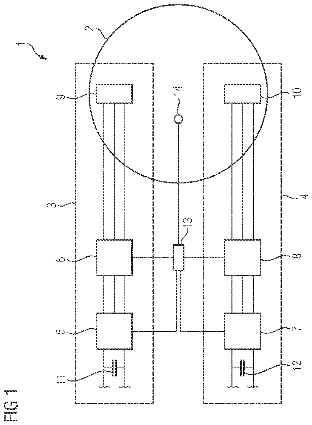
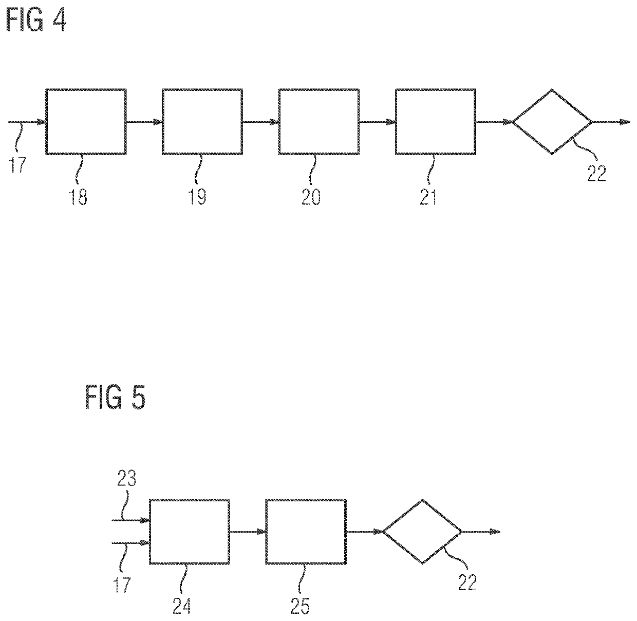
[0053]In FIG. 4 a block diagram of a method according to the invention is shown. As input variable, a measured signal 17 of a measurand, which describes the torque ripple of the electric machine 2, is used. The measured signal 17 can be measured by the sensor 14 of the electrical machine 2. The measurand can be, for instance, an acceleration measured by the sensor 14 at a stationary ring of a main bearing of the electrical machine 2.

[0054]In block 18, a low pass filtering eliminating a DC bias of the measured signal 17 occurs. After the low pass filtering, the measured signal 17 is high pass filtered in block 19 to remove any HF noise. From the filtered measured signal 17, an absolute value of a ripple in the measured signal 17 corresponding to an absolute value of the torque ripple amplitude is determined in block 20. In block 21, after determination of an absolute value of the ripple in the measured signal 17, a comparison value is determined by averaging the obtained absolute val...

second embodiment

[0056]In FIG. 5, a method according to the invention is depicted. The method can be conducted by the control unit 13 of the generator arrangement 1. As input variables, again the measured signal 17 measured by the sensor 14 is used. Additionally, a rotor speed signal 23, which is measured by a rotor speed sensor of the electrical machine 2 (not shown) or which is calculated and / or estimated by the control unit 13, is used. In block 24, an adaptive bandpass filtering of the measured signal 17 occurs. Thereby, a lower cutoff frequency and / or an upper cutoff frequency of the bandpass filtering can be adjusted depending on the rotor speed signal 23. By adjusting the lower cutoff frequency and / or the upper cutoff frequency of the bandpass filtering, a certain harmonic of the rotation of the rotor can be filtered from the measured signal. It is for instance possible that a second harmonic of the measured signal 17 is filtered. It is also possible that depending on a type of the electrical...


PUM


Abstract

Provided is a method for determination of a location of a short circuit fault in a generator arrangement, wherein the generator arrangement includes an electrical machine and at least one channel, wherein the or each channel includes a breaker, a converter unit and a set of stator windings of the electrical machine connected to the converter unit via the breaker, wherein upon an occurrence of a short circuit in a channel, the connection between the set of stator windings and the converter unit interrupted by opening the breaker, wherein depending on at least one measured signal of a measurand, wherein the measured signal is measured by at least one sensor of the electric machine and wherein the measurand describes a torque ripple of the electrical machine, either the electrical machine or the converter unit of the channel is determined as location of the short circuit fault.

Description

CROSS-REFERENCE TO RELATED APPLICATIONS[0001]This application claims priority to PCT Application No. PCT / EP2019 / 086822, having a filing date of Dec. 20, 2019, which is based on EP Application No. 18215481.5, having a filing date of Dec. 21, 2018, the entire contents both of which are hereby incorporated by reference.FIELD OF TECHNOLOGY[0002]The following relates to a method for determination of a location of a short circuit fault in a generator arrangement, wherein the generator arrangement comprises an electrical machine and at least one channel, wherein the or each channel comprises a breaker, a converter unit and a set of stator windings of the electrical machine connected to the converter unit via the breaker, wherein upon an occurrence of a short circuit in a channel, the connection between the set of stator windings and the converter unit is interrupted by opening the breaker. Furthermore, the following relates to a generator arrangement, a wind turbine, a computer program and...

Claims


Application Information

Patent Timeline
Patent Type & Authority Applications(United States)
IPC IPC(8): H02P29/024H02H7/06G01R31/34G01R31/52
CPCH02P29/024G01R31/52G01R31/343H02H7/06H02H3/042H02H7/1216H02P29/028
Inventor FREIRE, NUNO MIGUEL AMARALR PILLAI, RAHULWU, ZHAN-YUAN
Owner SIEMENS GAMESA RENEWABLE ENERGY AS
Why Eureka
Try Eureka