Process monitoring and control during laser-based refractive index modification of intraocular lenses in patients

a technology of laser-based refractive index and which is applied in the field of process monitoring and control during laser-based refractive index modification of intraocular lenses in patients, can solve the problems of less effective treatment, missed matching of existing matching, and left-over visual significant refractive error of cataract patients

Active Publication Date: 2022-01-20
AMO DEVMENT
View PDF0 Cites 0 Cited by
  • Summary
  • Abstract
  • Description
  • Claims
  • Application Information

AI Technical Summary

Benefits of technology

[0008]To achieve the above objects, the present invention provides a method for real-time process monitoring during laser-based refractive index modification of an intraocular lens (IOL), which includes: treating the IOL with a laser beam to modify a refractive index of a material of the IOL; while treating the IOL with the laser beam, measuring a signal from the IOL to determine a processing effect of the refractive index modification; and based on the determination, further treating the IOL with a laser beam. The signal measured from the IOL may be a fluorescent signal caused by the treatment laser, a fluorescent signal caused by an external illumination source, a temporary photodarkening effect, a color change, or a refractive index change directly measured by phase stabilized OCT.

Problems solved by technology

Despite all optimizations in modern pre-surgical diagnostic and IOL formula optimization, about 30% of cataract patients are left with visually significant refractive error after cataract surgery.
This may include spherical and cylindrical power misses but also misses in matching existing higher order aberrations like chromatic aberrations.
Reduced transmission of the laser through the cornea results in a less effective treatment.

Method used


Image

  • Process monitoring and control during laser-based refractive index modification of intraocular lenses in patients
  • Process monitoring and control during laser-based refractive index modification of intraocular lenses in patients
  • Process monitoring and control during laser-based refractive index modification of intraocular lenses in patients

Examples


first embodiment

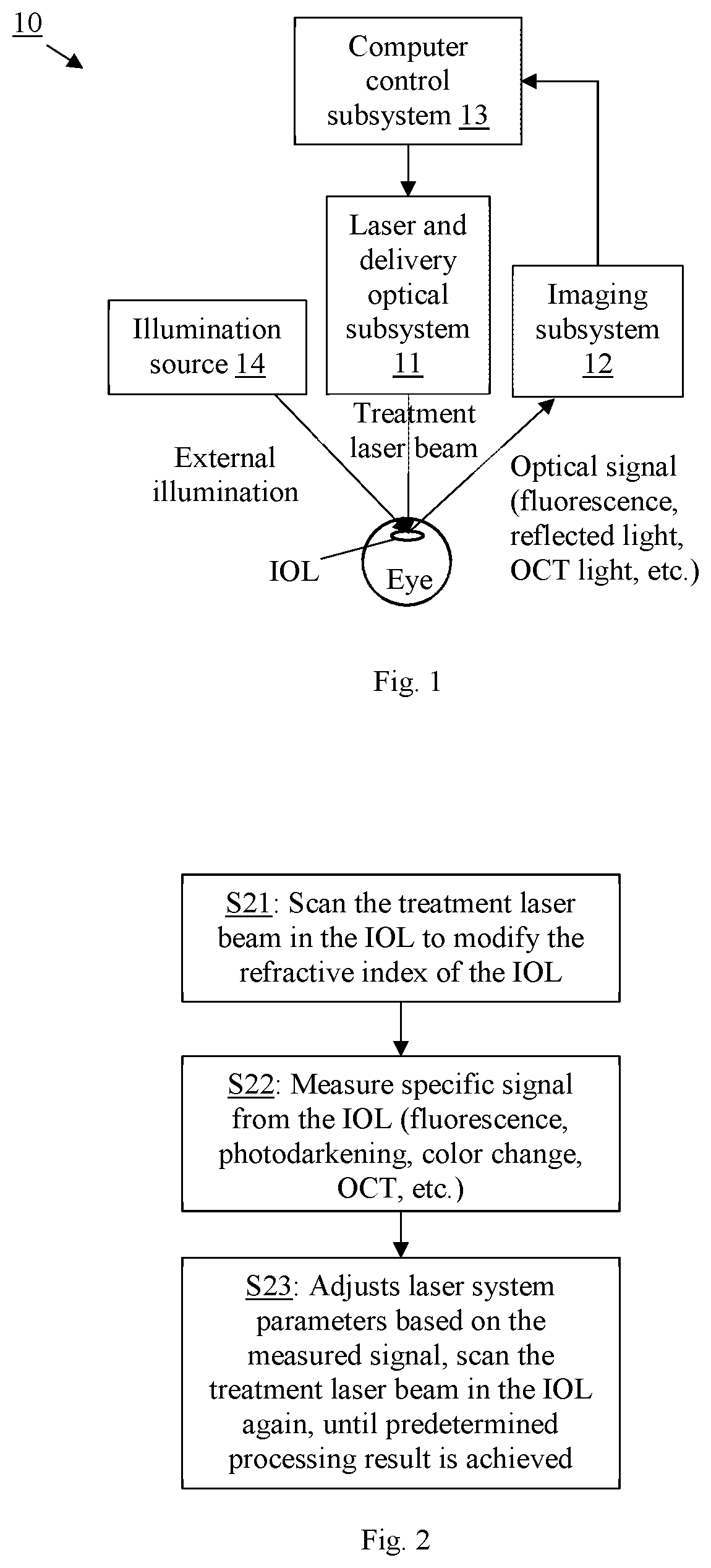
[0020]In the present invention, during in situ laser treatment of the IOL to modify the refractive index of the IOL material, while the treatment laser beam is scanned in the IOL, the treatment laser induced fluorescence (which may be referred to as autofluorescence) of the IOL material is measured and used as an indicator of the effectiveness of the laser induced processing of the IOL. The fluorescence signal can then be used to automatically adjust the treatment laser and optical subsystem 11 and perform further treatment so as to achieve the intended treatment outcome. Monitoring may be achieved by the imaging subsystem 12 which may use a video camera of the ophthalmic laser surgical system or a separate detector which is optimized for the detection of the induced fluorescence.

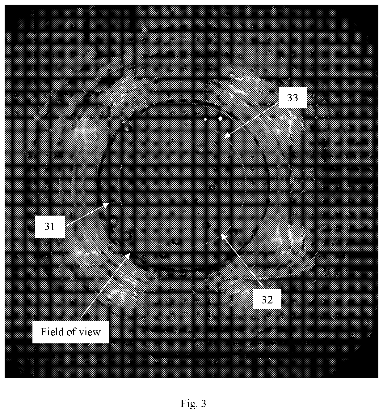
[0021]FIG. 3 shows an example of the aforementioned process monitoring conditions which allow optimization of the laser treatment process. This example shows the fluorescence signal 32 in the IOL material 3...

second embodiment

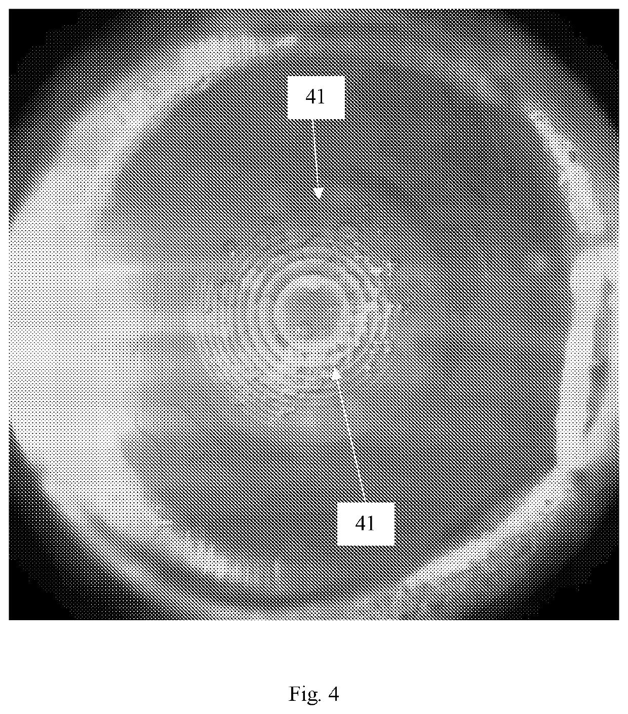
[0026]In the present invention, during in situ laser treatment of the IOL, an external fluorescence illumination source 14 (different from the treatment laser 11) is used to illuminate the IOL to induce fluorescence, which allows visualization of the fluorescence signal as indicator of the effectiveness of the laser induced processing of the IOL. The illumination (excitation) light wavelength may be optimized to maximize the efficacy of light conversion. The external illumination source 14 may be LEDs with an appropriate wavelength, or a secondary external laser light source with an appropriate wavelength. A wide range of excitation wavelengths are usable. Preferably, the excitation wavelengths are in the UV-blue spectrum range, and more preferably, between 360-410 nm. The imaging subsystem 12 may be a video camera of the ophthalmic laser surgical system or a separate detector optimized for the detection of the induced fluorescence.

[0027]FIG. 4 shows an example of a processed IOL 41...

third embodiment

[0032]In the present invention, during in situ laser treatment of the IOL, a temporary photodarkening effect, which is an effect of the chemical processing of the IOL, may be utilized as a process monitoring parameter. Preferably, retro-illumination (illumination from behind the IOL by light reflected from other structures of the eye) is used to produce images with better contrast. The more the refractive index change achieved in the IOL, the more the material will be darkened. The video camera (the imaging subsystem 12) of the ophthalmic laser system may be used to visualize and measure photodarkening effect as an indicator of the effectiveness of the laser induced processing of the IOL. Based on the observed photodarkening effect, the laser system may be adjusted and further treatment performed so as to correct possible transmission induced variances.

[0033]FIG. 6 shows the photodarkening during processing of the IOL with the femtosecond laser. With retro illumination, the Fresnel ...


PUM

PropertyMeasurementUnit
excitation wavelengthsaaaaaaaaaa
refractive indexaaaaaaaaaa
fluorescentaaaaaaaaaa

Abstract

Methods and related apparatus for real-time process monitoring during laser-based refractive index modification of an intraocular lens. During in situ laser treatment of the IOL to modify the refractive index of the IOL material, a signal from the IOL is measured to determine the processing effect of the refractive index modification, and based on the determination, to adjust the laser system parameters to achieve intended processing result. The signal measured from the IOL may be a fluorescent signal induced by the treatment laser, a fluorescent signal induced by an external illumination source, a temporary photodarkening effect, a color change, or a refractive index change directly measured by phase stabilized OCT.

Description

CROSS-REFERENCES TO RELATED APPLICATIONS[0001]This application is a non-provisional of and claims priority to U.S. Provisional Application Nos. 62 / 925,185, filed Oct. 23, 2019 and 62 / 832797, filed Apr. 11, 2019, which are incorporated herein by reference in their entirety.BACKGROUND OF THE INVENTIONField of the Invention[0002]This invention relates to a laser-based process of changing refractive properties of an implanted intraocular lens (IOL) by modification of the refractive index the IOL material, and in particular, it relates to process monitoring a control during laser-based in situ refractive index modification.Description of Related Art[0003]Despite all optimizations in modern pre-surgical diagnostic and IOL formula optimization, about 30% of cataract patients are left with visually significant refractive error after cataract surgery. This may include spherical and cylindrical power misses but also misses in matching existing higher order aberrations like chromatic aberratio...

Claims


Application Information

Patent Timeline
Patent Type & Authority Applications(United States)
IPC IPC(8): A61F9/008A61L27/16
CPCA61F9/00827A61F9/00834A61B2017/00061A61F2009/00851A61L27/16A61F2009/00844A61B2017/00154A61F2009/00897A61L2430/16
Inventor HOFER, RICHARDVANKOV, ALEXANDERWANG, JENNYDEWEY, DAVID A.GOODING, PHILLIPSCHUELE, GEORG
Owner AMO DEVMENT
Why Eureka
Try Eureka