Power supply control system and power supply control method

a power supply control system and power supply technology, applied in the direction of battery/fuel cell control arrangement, dc-ac conversion without reversal, battery/cell propulsion, etc., can solve the problem of battery over-charging or over-discharging, and achieve the effect of preventing an over-charging or over-discharging state of a battery

Pending Publication Date: 2022-01-27
HONDA MOTOR CO LTD
View PDF0 Cites 0 Cited by
  • Summary
  • Abstract
  • Description
  • Claims
  • Application Information

AI Technical Summary

Benefits of technology

[0016]According to aspects (1) to (7) described above, it is possible to prevent an over-charging or over-discharging state of a battery in each drive unit when two different drive units cooperate in parallel to drive an electric device using one inverter.

Problems solved by technology

However, when the AC-DC converter is shared, since driving one electric device by different drive units is not considered, the battery may be over-charged or over-discharged.

Method used


Image

  • Power supply control system and power supply control method
  • Power supply control system and power supply control method
  • Power supply control system and power supply control method

Examples


first embodiment

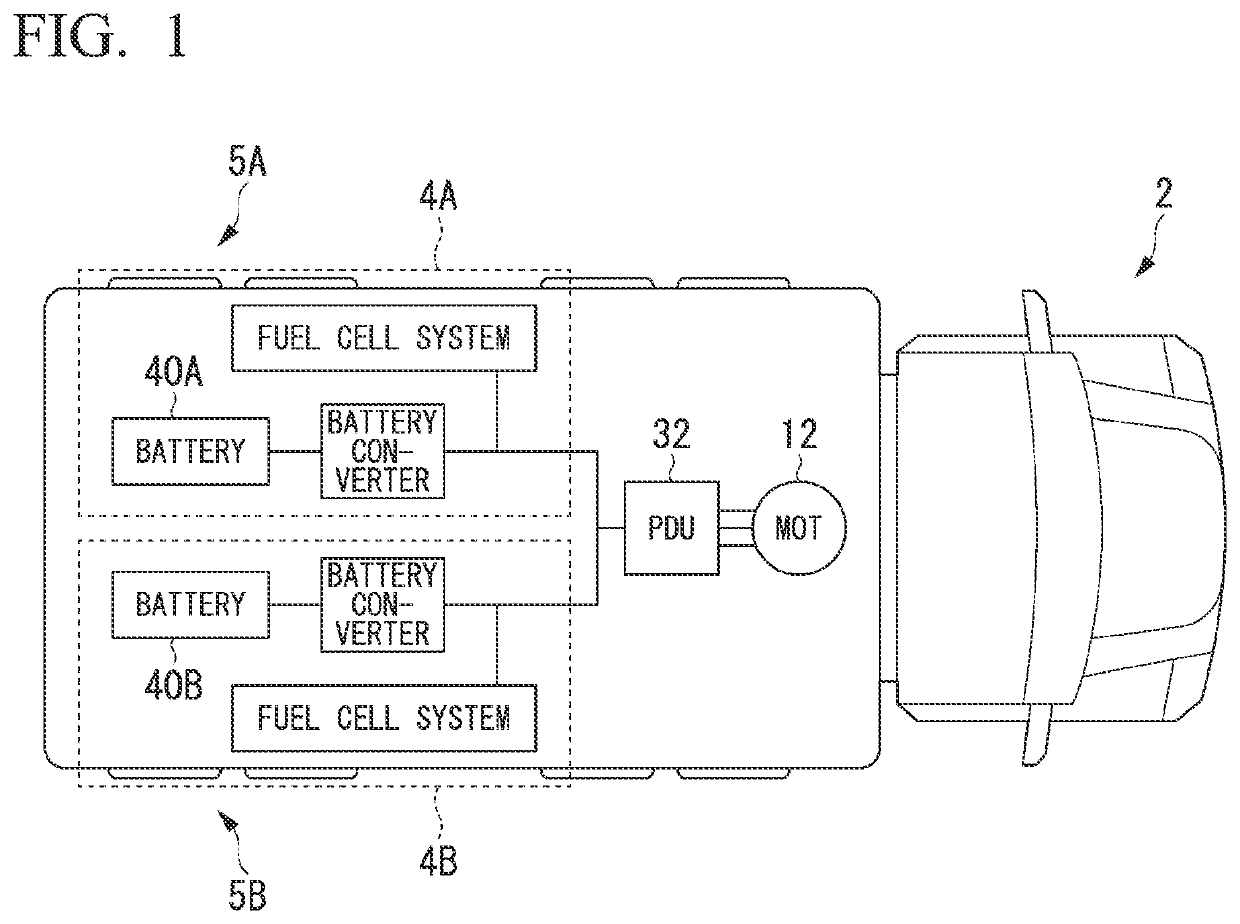
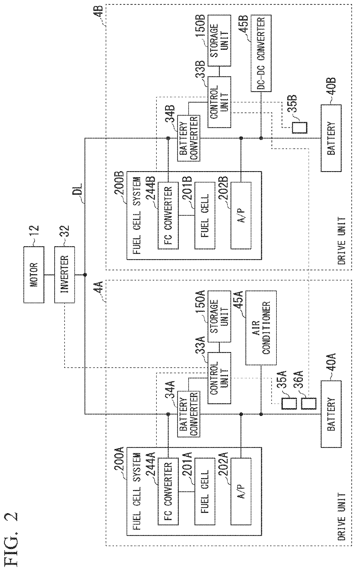
[0032]Next, a configuration example of the drive units 4A and 4B according to the first embodiment will be described. FIG. 2 is a block diagram illustrating an example of the configuration of the power supply control system including the drive unit 4 according to the present embodiment. As illustrated in FIG. 2, the power supply control system includes a motor (electric device) 12, an inverter (DC-AC converter) 32, a drive unit 4A, and a drive unit 4B. The drive unit 4A includes a fuel cell system 200A, a battery converter 34A, a control unit 33A, an air conditioner 45A, a battery 40A, a current sensor 35A, a current sensor 36A, and a storage unit 150A. The drive unit 4B includes a fuel cell system 200B, a battery converter 34B, a control unit 33B, a DC-DC conversion unit 45B, a battery 40B, a current sensor 35B, and a storage unit 150B.

[0033]The motor 12 is, for example, a three-phase AC electric motor. The rotor of the motor 12 is connected to the wheels 5A and 5B which are the dr...

second embodiment

[0111]Next, a configuration example of drive units 4A# and 4B# according to a second embodiment will be described. FIG. 9 is a block diagram illustrating an example of the configuration of a power supply control system including the drive unit 4# according to the second embodiment. As illustrated in FIG. 9, the power supply control system includes a drive unit 4A#, a drive unit 4B#, a motor 12, an inverter 32, a control unit 100, and a storage unit 150. The drive unit 4A# includes a fuel cell system 200A, a battery converter 34A, an air conditioner 45A, and a current sensor 35A. The drive unit 4B# includes a fuel cell system 200B, a battery converter 34B, a DC-DC conversion unit 45B, and a current sensor 35B. In the following description, when the drive units 4A# and 4B# are not distinguished from each other, they will be described as the drive unit 4# without adding A or B.

[0112]Hereinafter, configurations and operations of the second embodiment different from those of the first em...


PUM


Abstract

A power supply control system includes: an electric device; an inverter; a first drive unit including a first fuel cell system, a first voltage converter, and a first battery; a second drive unit including a second fuel cell system, a second voltage converter, and a second battery; and a control unit that controls the inverter and/or the first fuel cell system so that a first current value flowing through the first battery reaches a target value of the first current value and controls the second voltage converter and/or the second fuel cell system so that a second current value flowing through the second battery reaches the target value of the first current value.

Description

CROSS-REFERENCE TO RELATED APPLICATION[0001]Priority is claimed on Japanese Patent Application No. No. 2020-126683, filed Jul. 27, 2020, the content of which is incorporated herein by reference.BACKGROUND OF THE INVENTIONField of the Invention[0002]The present invention relates to a power supply control system and a power supply control method.Description of Related Art[0003]Conventionally, as a technology related to a fuel cell system mounted in a vehicle, a technology for controlling the power generation of the fuel cell system on the basis of the required power calculated on the basis of the accelerator depression amount, the temperature of a secondary battery, and the power storage amount is known (see, for example, Japanese Unexamined Patent Application, First Publication No. 2016-103460).[0004]As a configuration in which a plurality of fuel cell systems is mounted in one vehicle, a configuration in which an AC-DC converter, a fuel cell system, and a battery are provided for ea...

Claims


Application Information

Patent Timeline
Patent Type & Authority Applications(United States)
IPC IPC(8): B60L50/75H02J7/00
CPCB60L50/75B60L2210/40H02J7/0013H02J7/00714B60L50/50B60L58/40B60L58/30H02P27/06H02M7/42H02J2300/30H02J7/0063H02J2310/48H02J1/10H02J7/34Y02T10/70Y02T10/72Y02T90/40
Inventor KITAMOTO, RYOTASHIMIZU, KENICHIKUWANO, YUKI
Owner HONDA MOTOR CO LTD
Why Eureka
Try Eureka