System for localization of sound sources

a sound source and localization technology, applied in the field of sound and vibration, can solve the problem that the general estimate of the direction of the sound source is useless

Pending Publication Date: 2022-01-27
BSS APS
View PDF0 Cites 0 Cited by
  • Summary
  • Abstract
  • Description
  • Claims
  • Application Information

AI Technical Summary

Benefits of technology

[0015]Such system is advantageous and solves the mentioned problem, since the combination of using a lizard ear mimicking algorithm and an RF link to transmit a time synchronization signal to slave units has been found to provide a reliable sound source localization. This allows the slave units with sound sensors to be connected wirelessly to the master unit. The lizard ear mimicking algorithm, see e.g. WO 2010 / 149167 A1, can provide a reliable localization result even with short sound sequences of such as 0.2-2 seconds. This can be transmitted in one data packet via a wireless RF link. Thus, it is possible to provide a time synchronization signal via RF to ensure sufficient time alignment of the slave units, at least within a distance of such as 10 m, to produce time aligned time sequences for successful localization. I.e. at distances at least up to such as 10 m, it can be ensured that the same time signal transmitted to all slave units are received simultaneously or at least within a very narrow time window, at all slave units, thus ensuring time aligned time sequence recordings.
[0023]The recording system is arranged to store time sequences having a fixed length of within 0.1-10 seconds, such as 0.2-2 seconds. This has been found to be sufficient time for a lizard ear mimicking algorithm to function reliably, and thus it is possible to ensure good time alignment when only short time sequences are required from the slave units. Further, it is easy to transmit such short time sequences in one single RF transmission packet, thereby allowing quickly repeating localization estimates.
[0025]The time synchronization signal may be a periodic signal with a fixed frequency of within 100 Hz to 5 kHz, such as within 300 Hz and 3 kHz. The periodic signal may be a square wave signal, e.g. with a 50% duty cycle, a chirp signal or even a random white noise signal, and wherein the time alignment by the slave unit is performed to a rising or falling edge of the square waves. A random white noise signal has proven to be advantageous in case of environments with a high degree of reflections.

Problems solved by technology

This constitutes a problem, since normal wireless data packet communication suffers from the fact that sound processing involved in localization based on captured sound signals at different positions is sensitive with respect to time matching of the sound signals.
If the time matching is unreliable, the sound source direction estimate will in general be useless.

Method used


Image

  • System for localization of sound sources
  • System for localization of sound sources

Examples


Embodiment Construction

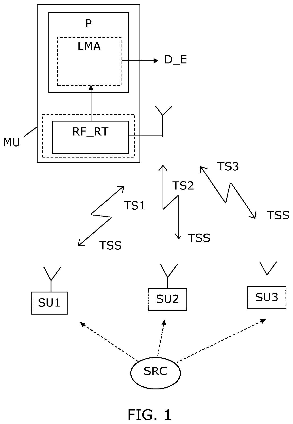
[0049]FIG. 1 shows a block diagram illustrating in simple form a sound source localization system embodiment with three slave units SU1, SU2, SU3 positioned at different locations, and a master unit MU. A sound source SRC generates an acoustic signal (dashed lines) which is received by microphones in the three slave units SU1, SU2, SU3. The master unit MU has an RF receiver and and RF transmitter, here shown as on unit RF_RT. The RF transmitter part RF_RT can transmit an airborne wireless RF signal with a time synchronization signal TSS represented therein, e.g. a square wave signal with a frequency between 200 Hz and 2,000 Hz. The RF signal may be transmitted at an RF link with a carrier frequency of e.g. 433 MHz. RF receivers in the slave units SU1, SU2, SU3 receive the time synchronization signal TSS approximately at the same time due to the RF transmission, and this time synchronization signal TSS is then used to set timing of a recording of the acoustic signal from the sound so...


PUM


Abstract

A sound or vibration source localization system with a master unit and a plurality of slave units. The master unit transmit a time synchronization signal via an RF link to the slave units. A microphone or vibration sensor in each of the slave units are used to record a short time sequence, e.g. 0.2-2 seconds, of sound or vibration time aligned with the time synchronization signal to ensure synchronous recording of the time sequences at all slave units. The slave unit transmit the recorded time aligned time sequences via an RF link along with a time stamp and an identification code to the master unit. The master unit has a processor system arranged to process the received time sequences from the slave units according to a lizard ear mimicking algorithm. Such type of algorithm provides a good direction estimate in response to two input signals recorded at different positions, even with a short time sequence. As a result, and preferably along with information regarding physical positions of the slave units, a sound source or vibration source localization estimate can be generated.

Description

FIELD OF THE INVENTION[0001]The present invention relates to the field of sound and vibration, and to estimation of localization (e.g. direction and / or position) of a sound or vibration source based processing of two captured sound or vibration signals at different positions.BACKGROUND OF THE INVENTION[0002]Precise and fast localization of a sound source has a number of applications. Either in a stationary setting, e.g. for incoming emergency vehicles to control traffic lights, detection of incoming Unmaned Aerial Vehicles (UAVs), e.g. drones, or for robotic navigation in response to a voice or other sound sources. Such systems require at least two sound sensors, and preferably for reliable operation and e.g. 3D localization, in general an array of a significant number of sound sensors may be required. Several processing methods exist to process two sound input signals and determining a sound source direction accordingly.[0003]However, for many applications, it is a requirement for ...

Claims


Application Information

Patent Timeline
Patent Type & Authority Applications(United States)
IPC IPC(8): G01S5/20G01S5/00G01S5/22
CPCG01S5/20G01S5/22G01S5/0081G01S5/18G01S3/808G08G1/0965G08G1/0116G08G1/0133G08G1/0145
Inventor HALLAM, JOHNCHRISTENSEN-DALSGAARD, JAKOBSHAIKH, DANISHHELLE, MADS
Owner BSS APS
Why Eureka
Try Eureka