System and instrument for delivering an object and method for detecting delivery

a technology of system and instrument, applied in the field of system and instrument for delivering an object and detecting delivery, can solve the problems of inability to meet the requirements of the patient, so as to reduce the error proneness of electromagnetic interference

Active Publication Date: 2016-10-20
KONINKLJIJKE PHILIPS NV
View PDF1 Cites 0 Cited by
  • Summary
  • Abstract
  • Description
  • Claims
  • Application Information

AI Technical Summary

Benefits of technology

[0008]It is an object of the present invention to allow for a providing of an object in a body and a detecting thereof while avoiding the drawbacks on the known approaches, e.g. giving an opportunity for reliable localization in ultrasound images used for real-time monitoring of a medical procedure with reduced error proneness to electromagnetic interference.
[0026]A complete enclosure in the form of, for example, a cylinder arranged around the portion(s) of the instrument, provides the benefit that there is no additional influence of the orientation of the instrument relative to the ultrasound probe, in contrast to a partial enclosure or a provision of the ultrasound transducer(s) just beside the instrument portion.
[0028]Of the piezomaterials for the ultrasound transducers copolymer-materials and specifically sol-gel solutions are particularly preferred as they provide the advantage that the resulting ultrasound transducers (or sensors) can be made conformable to an object regardless of its curvature. In particular, these materials can be deposited on the outside of a needle or other instrument and the needle (or other instrument) stays smooth; while additionally the lumen of the needle (or other instrument) stays free for delivering objects (e.g. brachytherapy seeds).

Problems solved by technology

Source placement errors are common due to factors such as tissue motion and deformation, needle bending, human error, etc.
However, deviations from the plan are inevitable due to problems such as prostate motion and deformation caused by needle insertion, prostate edema, needle bending and human and calibration errors.
At this stage, significant deviations from the plan, if detected, should be fixed by repeated treatment which is costly and time consuming.
Source localization in ultrasound is hindered by low quality of ultrasound images, shadowing, missing sources and false positives due to calcifications and air bubbles.
However, the EM technology is prone to error due to magnetic field interference from a plethora of metallic objects in the operating room.

Method used


Image

  • System and instrument for delivering an object and method for detecting delivery
  • System and instrument for delivering an object and method for detecting delivery
  • System and instrument for delivering an object and method for detecting delivery

Examples


Embodiment Construction

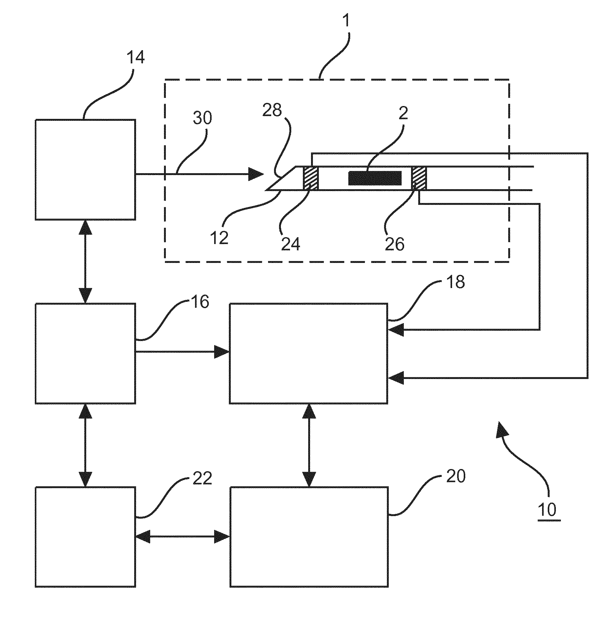
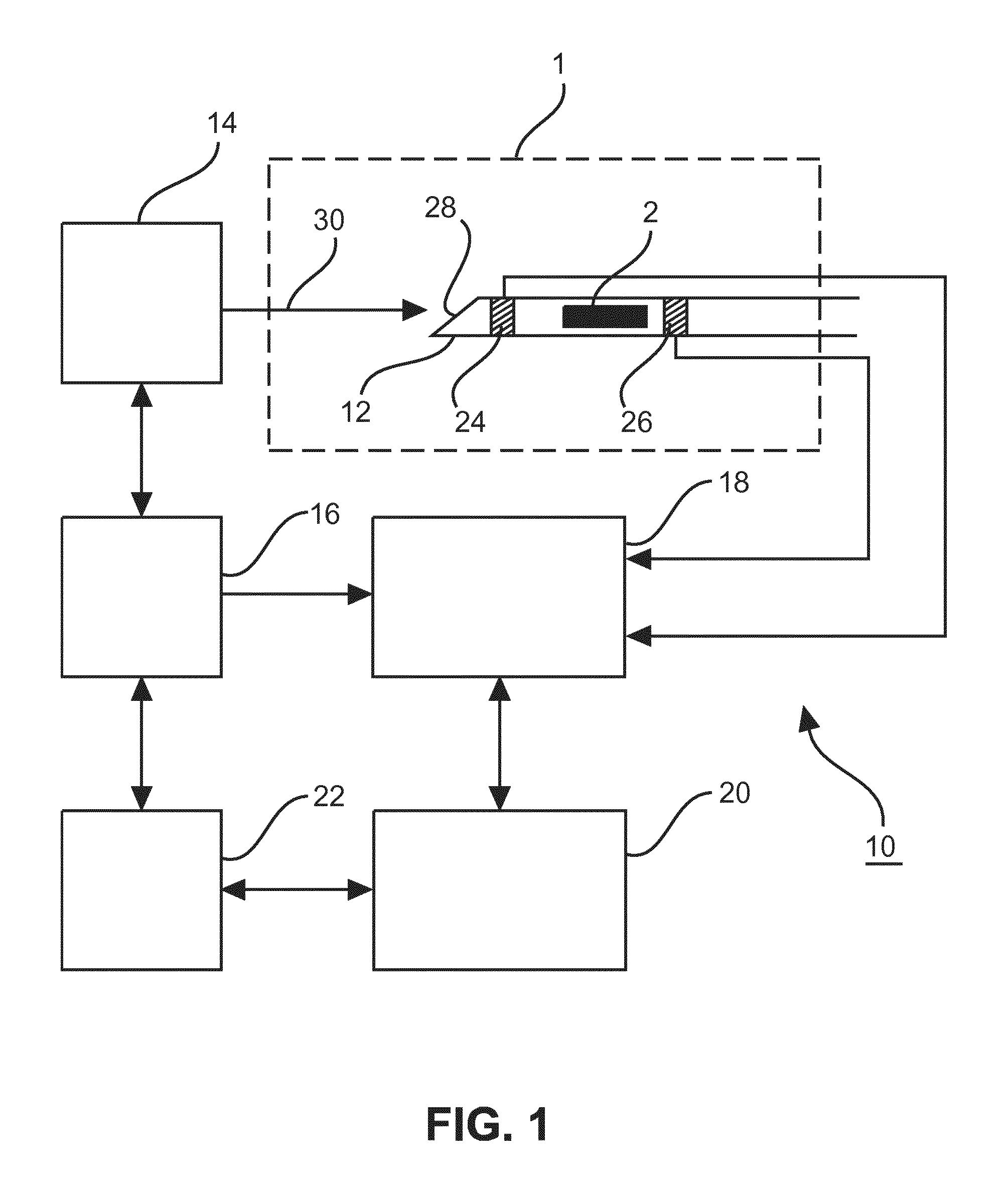
[0048]FIG. 1 shows a schematic illustration of a system 10 for providing an object 2 in a body 1 in accordance with an embodiment of the invention.

[0049]The system 10 includes a needle 12 as the instrument for delivering the object 2 into the body 1, an ultrasound probe 14, a control unit 16 for the ultrasound probe 14, a processor 18 coupled to the control unit 16, a delivery management unit 20 coupled to the processor 18 and an interface 22 for interacting with a user of the system 10.

[0050]The object 2 is a radioactive source used for brachytherapy of the body 1.

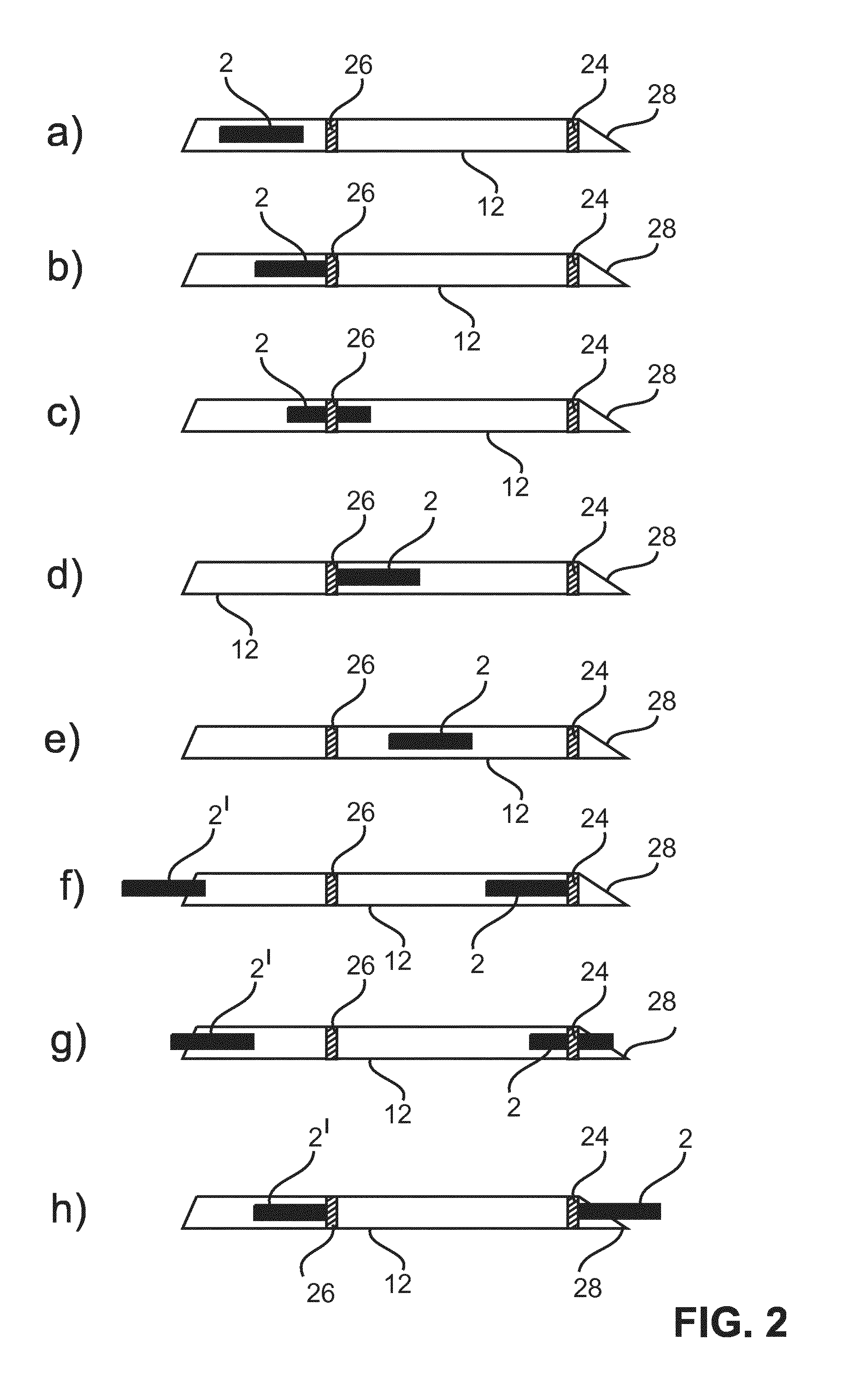
[0051]The needle 12 is hollow for allowing the delivery of the object 2 into the body and is provided with two ultrasound transducers 24, 26, wherein one ultrasound transducer 24 is arranged close to a tip 28 of the needle 12 through which the object 2 is released into the body 1, while the other ultrasound transducer 26 is arranged distant to the one ultrasound transducer 24 opposite to the tip 28. As schematically shown...


PUM


Abstract

The invention relates to a system (10) for providing an object (2) in a body (1), a processor (18) arranged to be used in the system (10) for providing an object (2) in a body (1), an instrument (12) for providing an object (2) into a body (1), a method for detecting a providing of an object (2) in a body (1) and a software product for detecting a providing of an object (2) in a body (1). In order to allow for a providing of an object (2) in a body (1) and a detecting hereof while avoiding the drawbacks on the known approaches, e.g. giving an opportunity for reliable localization in ultrasound images used for real-time monitoring of a medical procedure with reduced error proneness to electromagnetic interference, the invention utilizes the finding that the characteristics of a reception or transmission of an ultrasound transducer (24, 26) are influenced by the surrounding environment of the ultrasound transducer (24, 26). By detecting changes in the characteristics the presence or absence of an object (2) to be provided at the ultrasound transducer (24, 26) is determined.

Description

FIELD OF THE INVENTION[0001]The invention relates to a system for providing an object in a body, a processor arranged to be used in the system for providing an object in a body, a method for detecting a providing of an object in a body and a software product for detecting a providing of an object in a body.BACKGROUND OF THE INVENTION[0002]US 2013 / 0253387 A1 discloses a system for applying vibratory energy to pathologic material in a treatment area of a body. The system comprises an energy source configured to provide an energy signal, a piezoelectric transducer configured to receive the energy signal and an effector operatively coupled to the transducer, wherein the effector has a proximal end connected to a handle and a distal portion configured to apply the vibratory energy to the pathologic material. The system further comprises a cannula having a longitudinal passage to receive at least a portion of the effector and being configured to expose at least the distal portion of the e...

Claims


Application Information

Patent Timeline
Patent Type & Authority Applications(United States)
IPC IPC(8): A61B8/08A61B34/20A61N5/10A61B8/12A61B8/00
CPCA61B8/0841A61B8/12A61B8/4483A61B8/5207A61N5/1007A61B2034/2063A61N5/1064A61B34/20A61N5/103A61B8/463A61N5/1071A61B8/4494A61B2090/392A61B2090/3925A61N5/1027
Inventor DEHGHAN MARVAST, EHSANVIGNON, FRANCOIS GUY GERARD MARIEJAIN, AMEET KUMARBHARAT, SHYAMTAHMASEBI, AMIRBINNEKAMP, DIRK
Owner KONINKLJIJKE PHILIPS NV
Why Eureka
Try Eureka