Eureka AIR delivers breakthrough ideas for toughest innovation challenges, trusted by R&D personnel around the world.

Permanent magnet direct-current electric motor

Pending Publication Date: 2022-02-03
GUANGDONG ZHAOQING L&V
View PDF0 Cites 0 Cited by
  • Summary
  • Abstract
  • Description
  • Claims
  • Application Information

AI Technical Summary

Benefits of technology

The present application provides a new method for improving the EMC level of the motor by defining the surface magnetic curve of the magnetic cylinder without installing any new components or increasing the processing and manufacturing costs. The method has the advantage of low cost and easy implementation. The technical solution achieves a better balance among the installation space of the motor, the cost of magnetic materials, and the performance of the motor by reducing the amount of NdFeB materials.

Problems solved by technology

The application environment of permanent magnet DC motor leads to a need for low noise and vibration.
For all kinds of products driven by small permanent magnet DC motors, there are usually only EMI problems, while EMI can be divided into conducted interference and radiated interference.
However, none of the above measures can effectively suppress EMI, because it will either increase the cost of the motor or weaken other performances of the motor.
For a round structure, although the manufacturing is convenient and the space required for installation is relatively small, it is necessary to additionally set up fixing element(s) to fix the motor, so as to prevent it from rotating as a whole, which increases the demand for installation space and the complexity of installation.
For a square structure, it can naturally prevent the motor from rotating due to the sides, but there are two problems for such a shape: in some irregular installation spaces, it may be difficult to install simply for the interference of a certain corner; due to the round shape of the rotor, the volume of the magnetic cylinder with a square outer contour and a circular inner contour is much larger at the corners than the volume between two adjacent corners, which makes the distribution of magnets extremely uneven, obviously reduces the motor performance, and leads to the waste of magnetic materials at the corners of the magnetic cylinder.

Method used


Image

  • Permanent magnet direct-current electric motor
  • Permanent magnet direct-current electric motor
  • Permanent magnet direct-current electric motor

Examples


Embodiment Construction

[0021]The following is a detailed description of the technical solutions of the present application with reference to the accompanying drawings.

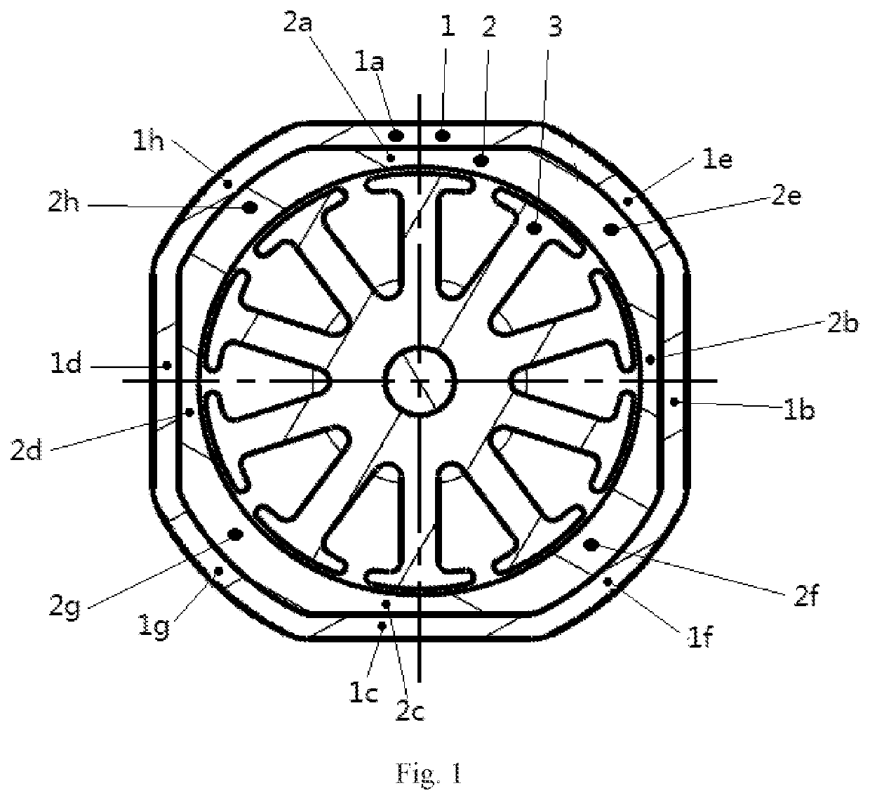
[0022]Referring to FIG. 1, the permanent magnet DC motor of the present application comprises a stator assembly and a rotor assembly, wherein the stator assembly comprises a housing 1 and a magnetic cylinder 2, and the rotor assembly comprises a rotor 3. The rotor 3, magnetic cylinder 2 and housing 1 are arranged sequentially from inside to outside. The rotor 3 is provided on a rotor shaft (not shown), which serves as an output shaft. Rotor 3 includes rotor poles and windings. The rotor 3 has a circular outer peripheral on which a magnetic cylinder 2 is arranged. The inner wall profile of the magnetic cylinder 2 is circular and its diameter is slightly larger than the outer diameter of the rotor 3, that is, there is an air gap between the inner wall of the magnetic cylinder 2 and the outer peripheral of the rotor 3. In FIG. 1, there are four...


PUM


Abstract

The present application relates to a permanent magnet DC motor, which comprises a stator assembly and a rotor assembly, wherein the stator assembly comprises a housing and a magnetic cylinder, and the rotor assembly comprises a rotor; the rotor, the magnetic cylinder and the housing are sequentially arranged from inside to outside; the ratio of an angle corresponding to a commutation section of the surface magnetic curve of the magnetic cylinder to the corresponding angle of the surface magnetic curve of the corresponding magnetic pole is less than or equal to 15%; and the outer peripheral contour of the magnetic cylinder is based on a regular polygon, and curves are arranged at the connections of sides of the regular polygon to smoothly connect the sides of the regular polygon. The motor of the present application reduces the noise and vibration of the motor and improves its EMC level.

Description

TECHNICAL FIELD[0001]The present application relates to the field of motors, and particularly relates to a permanent magnet DC motor.BACKGROUND ART[0002]Permanent magnet DC motors are widely used in various portable electronic equipment or other devices. With the continuous improvement of intelligence and comfort of automobiles, permanent magnet DC motors are widely used in automobiles, such as multi-directional adjustment of seats and adjustment of windows. The application environment of permanent magnet DC motor leads to a need for low noise and vibration. In addition, there is a high requirement for the Electro Magnetic Compatibility (EMC) level of permanent magnet DC motors when used in automobiles due to the presence of various electronic devices in automobiles, to avoid any effect on the normal operation of automobiles. EMC, according to its contents, can be divided into electromagnetic interference (EMI) and electromagnetic sensitivity (EMS). For all kinds of products driven ...

Claims


Application Information

Patent Timeline
IPC IPC(8): H02K11/02H02K1/17H02K23/04
CPCH02K11/02H02K23/04H02K1/17H02K2213/03
Inventor GONG, HONGYUFENG, CHENTIAN, LICHEN, LIANGYAN, MINGCHU
Owner GUANGDONG ZHAOQING L&V
Why Eureka
Eureka Blog
Learn More