
Method for operating a coating installation for producing layer systems

a technology for coating installations and production lines, applied in applications, instruments, other domestic objects, etc., can solve the problems of inability to perform iterative trial and error processes that can only be performed, cannot be easily maintained, and only be successfully carried out by well-trained operators or skilled personnel, so as to achieve a high degree of certainty and carry out more effectively

Pending Publication Date: 2022-02-17
RODENSTOCK GMBH
View PDF0 Cites 0 Cited by
  • Summary
  • Abstract
  • Description
  • Claims
  • Application Information

AI Technical Summary

Benefits of technology

The patent is about a device that filters visible light to improve image quality. The device can adjust different filter properties and the speed at which the light passes through the device. This allows for optimal control over the image, making it suitable for a wide range of applications. The software program controls the coating installation and can work with different data processing systems. The technical effects of this patent are improved image quality and flexibility in design options for filters and slew rate.

Problems solved by technology

These deviations are due to the fact that the condition of the coating installation changes slightly, for example due to deposits of coating material on the walls of the vacuum chamber, operator influences when loading the coating installation with coating material, wear of various components installed in the coating installation and the like.
Such process maintenance requires in-depth know-how and can so far only be carried out successfully by well-trained operators or skilled personnel.
This method is often a time and material consuming iterative trial and error process that can only be performed by knowledgeable operators.
This described experience-based procedure will not always lead reliably to the desired result.
Furthermore, experience-based process maintenance does not always lead to the same layer thickness relations for the same optical colour values.
This can lead to unknowingly changing layer properties and layer thickness relations.

Method used


Image

  • Method for operating a coating installation for producing layer systems
  • Method for operating a coating installation for producing layer systems
  • Method for operating a coating installation for producing layer systems

Examples


Embodiment Construction

[0212]In the figures, components of the same kind or having the same effect are numbered with the same reference signs. The figures merely show examples and are not to be understood as limiting.

[0213]Directional terminology used in the following, with terms such as “left”, “right”, “upper”, “lower”, “before”, “behind”, “after” and the like, is merely intended to facilitate understanding of the figures and is in no way intended to represent a limitation of generality. The components and elements depicted, their design and use can vary according to the considerations of a person skilled in the art and can be adapted to the respective applications.

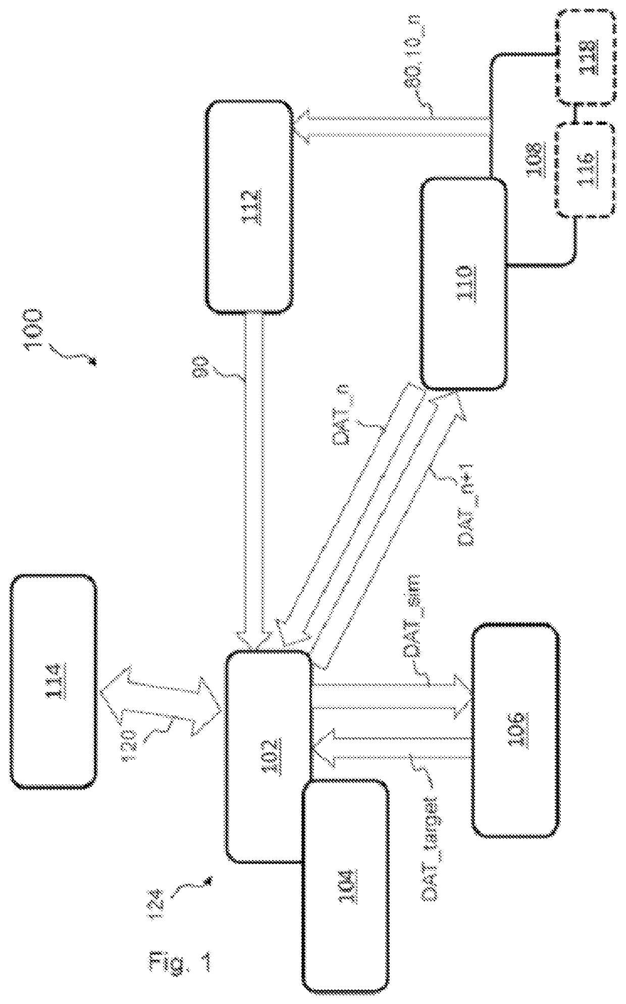
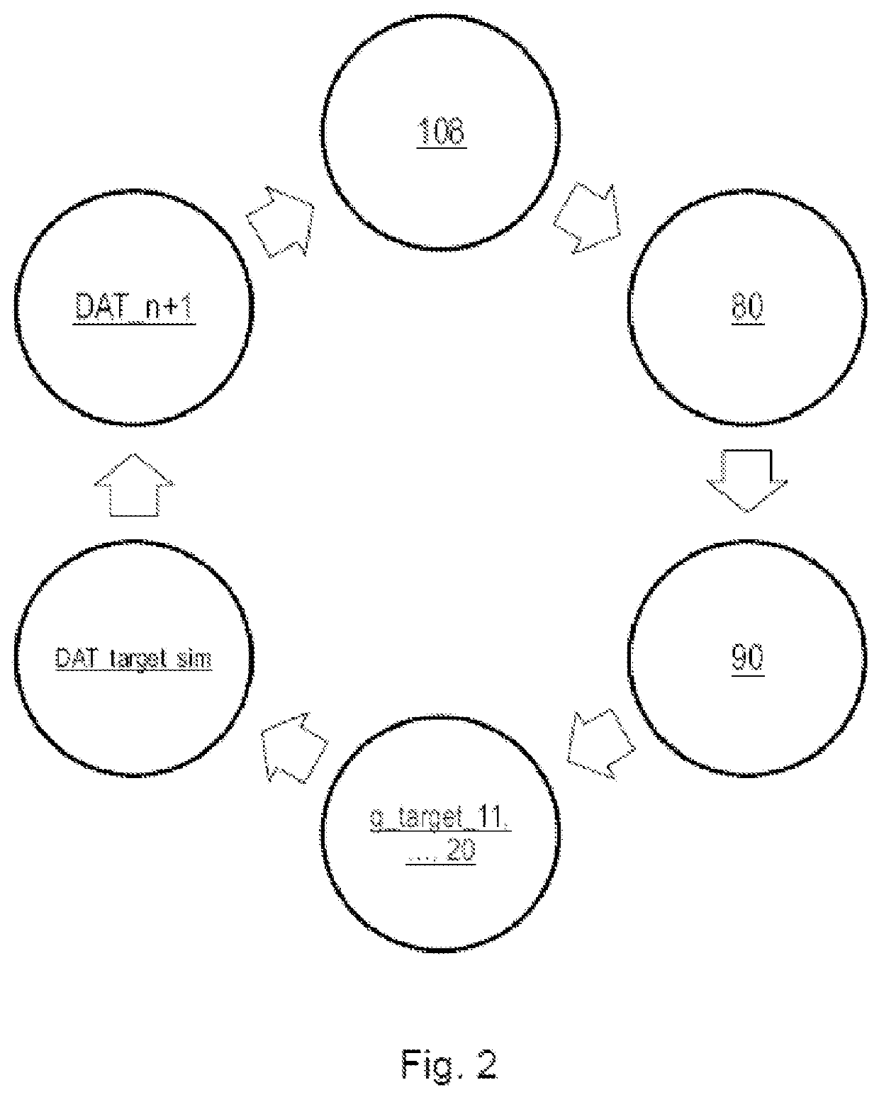
[0214]FIG. 1 shows a block diagram of a coating system 100 according to an example embodiment of the invention. Advantageously, the coating system 100 can be operable with a self-controlling and feedback control process. The coating system 100 for the production of a layer system 10 for an optical element 80 comprises at least one coating ins...


PUM

PropertyMeasurementUnit
hue angleaaaaaaaaaa
hue angleaaaaaaaaaa
hue angleaaaaaaaaaa

Abstract

A self-controlling feedback method for operating at least one coating installation for producing layer systems, a method for producing a layer system in at least one coating installation, a method for running in a coating process in at least one coating installation for producing a layer system, a coating system for producing a layer system, a coating installation for producing a layer system, a system of coating installations for producing layer systems, a database for storing installation datasets, a computer program product for a method for operating at least one coating installation, and a data processing system for executing a data processing program are disclosed.

Description

PRIOR ART[0001]The invention relates to a method for operating a coating installation for the production of layer systems. The invention further relates to a method for the production of a layer system, a method for running-in a coating process in a coating installation, a coating system, a system of coating installations, and a database for storing installation data sets, a computer program product for a method for operating a coating installation, and a data processing system for the execution of a method for operating a coating installation for the production of layer systems.[0002]A coating method implemented in a manufacturing environment with an underlying coating process typically has variations from coating batch to coating batch. These deviations are due to the fact that the condition of the coating installation changes slightly, for example due to deposits of coating material on the walls of the vacuum chamber, operator influences when loading the coating installation with...

Claims


Application Information

Patent Timeline
Patent Type & Authority Applications(United States)
IPC IPC(8): C23C14/54G01B11/06G02B1/115G02B27/00C23C16/52
CPCC23C14/54G01B11/0616C23C16/52G02B27/0012G02B1/115B29D11/00865B29D11/00009
Inventor SCHERSCHLICHT, RÜDIGERRADÜNZ, STEFAN
Owner RODENSTOCK GMBH
Learn More