
Working machine

Pending Publication Date: 2022-02-17
KUBOTA LTD
View PDF8 Cites 3 Cited by
  • Summary
  • Abstract
  • Description
  • Claims
  • Application Information

AI Technical Summary

Benefits of technology

The invention relates to a working machine that has a cooling system that consumes a lot of power, reducing the machine's ability to work. To address this issue, the invention increases the machine's power output to improve its performance. Additionally, the invention adjusts the speed of the machine's fan based on the engine's rotation speed, ensuring good performance at both high and low engine speeds.

Problems solved by technology

As a result, workability of the machine is reduced.

Method used


Image

  • Working machine
  • Working machine
  • Working machine

Examples


Embodiment Construction

[0041]An embodiment of the present invention will be described below with reference to drawings.

[0042]FIG. 13 shows a side view of a working machine 1 according to the present invention. FIG. 13 shows a compact track loader as an example of the working machine 1. However, the working machine 1 is not limited to a compact track loader, and may be another kind of loader, such as a skid steer loader. The working machine 1 may be a working machine other than the loader.

[0043]As shown in FIG. 13, the working machine 1 includes a machine body 2, a cabin 3, a working device 4, and a pair of traveling devices 5.

[0044]The cabin 3 is mounted on the machine body 2. The cabin 3 incorporates an operator's seat 8 on which an operator sits. The working device 4 is attached to the machine body 2. The pair of traveling devices 5 are disposed on outsides of the machine body 2. A prime mover 6 is mounted internally on a rear portion of the machine body 2.

[0045]In the present embodiment, a forward dire...


PUM


Abstract

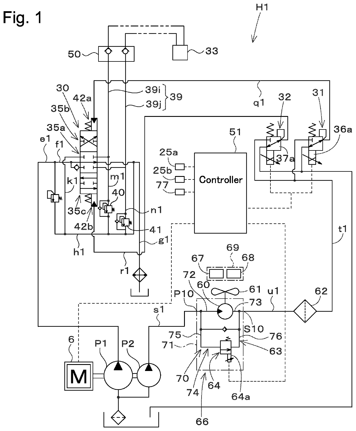
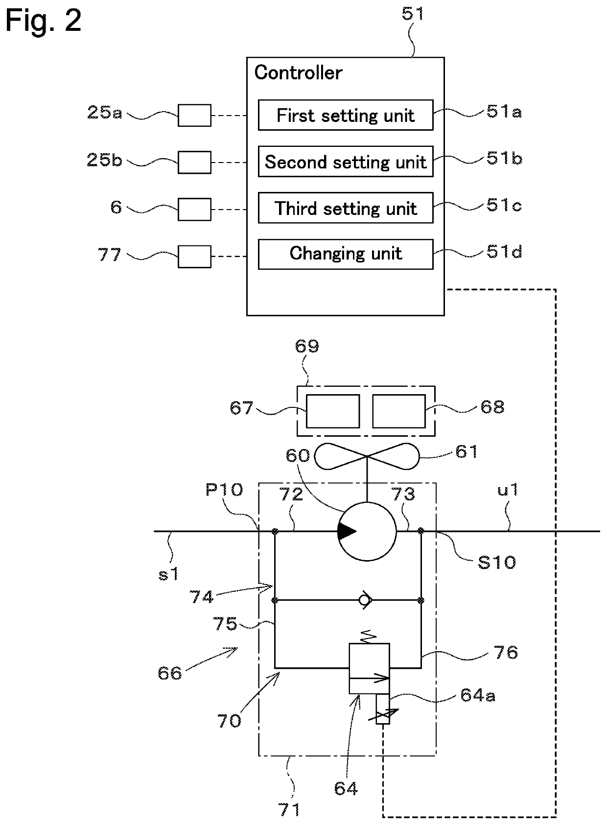
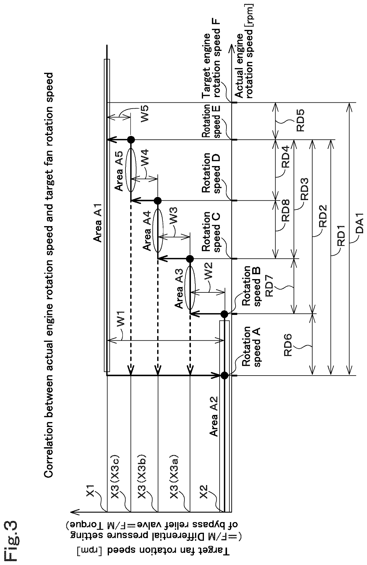
A working machine includes a prime mover, a hydraulic pump driven by power of the prime mover, a cooler including a cooling fan rotated by either the power of the prime mover or hydraulic fluid delivered from the hydraulic pump, and a controller configured or programmed to perform a reduction control for reducing a target fan rotation speed that is a target rotation speed of the cooling fan in response to reduction of an actual prime mover rotation speed that is an actual rotation speed of the prime mover, and to perform, after the reduction control, a restoration control for restoring the target fan rotation speed. The controller is configured or programmed to make a difference between a reduction rate of the target fan rotation speed in the reduction control and an increase rate of the target fan rotation speed in the restoration control.

Description

FIELD OF THE INVENTION[0001]The present invention relates to a working machine.DESCRIPTION OF THE RELATED ART[0002]A working machine disclosed in Japanese Unexamined Patent Publication No. 2016-145493 is known.[0003]The working machine disclosed in Japanese Unexamined Patent Publication No. 2016-145493 includes a working device and a traveling device that are driven by a power of a prime mover, and the devices perform work operations. In addition, the working machine includes a hydraulic pump that is driven by the power of the prime mover, and drives a cooler configured to cool cooled objects such as an oil cooler and a radiator with hydraulic fluid delivered from the hydraulic pump.SUMMARY OF THE INVENTION[0004]In the working machine disclosed in Japanese Unexamined Patent Publication No. 2016-145493, horsepower is consumed by the cooling system in heavy-duty work where a load on the prime mover is large, and thus the horsepower available for the working device and the traveling de...

Claims


Application Information

Patent Timeline
IPC IPC(8): F15B21/02
CPCF15B21/02F15B2211/62F01P7/044F15B21/0423F15B2211/20576F15B2211/327F15B2211/329F15B2211/355F15B2211/6355F15B2211/611F15B2211/615F15B2211/7058F15B2211/75F15B2211/20515F15B2211/20523F15B2211/6343F15B2211/6651F15B2211/633F15B2211/515F15B2211/526F15B2211/513F15B2211/50518F15B2211/6346E02F9/226E02F9/2282E02F9/2292F01P2025/32F01P2025/50F01P2025/40E02F9/2246
Inventor ABE, DAIKIFUKUDA, YUJINAKAGAWA, HIROAKIHAMAMOTO, RYOTA
Owner KUBOTA LTD
Features
  • Generate Ideas
  • Intellectual Property
  • Life Sciences
  • Materials
  • Tech Scout
  • Unparalleled Data Quality
  • Higher Quality Content
  • 60% Fewer Hallucinations
Learn More