Transistor with reduced gate resistance and improved process margin of forming self-aligned contact

a technology of self-aligning contact and gate resistance, which is applied in the direction of semiconductor devices, semiconductor/solid-state device details, electrical apparatus, etc., can solve the problems of reliability, source/drain contact structure to conductive material shorts, dielectric breakdown, etc., and achieve the effect of increasing gate resistance and reducing the volume of conductive materials

Active Publication Date: 2022-02-17
NAN YA TECH
View PDF1 Cites 0 Cited by
  • Summary
  • Abstract
  • Description
  • Claims
  • Application Information

AI Technical Summary

Benefits of technology

[0026]Due to the design of the semiconductor device of the present disclosure, the first conductor and the second conductor are formed to prevent the erosion of the self-aligned dielectric cap corner. In addition, it may prevent source / drain contact which can lead to source / drain contact structure to conductive material shorts and dielectric breakdown (i.e., reliability) issues. A thick self-aligned dielectric cap which may be kept by the first conductor and the second conductor also means deep conductive material recess, which reduces the conductive material volume and thus increases gate resistance.

Problems solved by technology

As a result, the self-aligned dielectric cap has to be thick enough to prevent source / drain contact which can lead to source / drain contact structure to conductive material shorts and dielectric breakdown (i.e., reliability) issues.
In addition, it may prevent source / drain contact which can lead to source / drain contact structure to conductive material shorts and dielectric breakdown (i.e., reliability) issues.

Method used


Image

  • Transistor with reduced gate resistance and improved process margin of forming self-aligned contact
  • Transistor with reduced gate resistance and improved process margin of forming self-aligned contact
  • Transistor with reduced gate resistance and improved process margin of forming self-aligned contact

Examples


Embodiment Construction

[0049]The following disclosure provides many different embodiments, or examples, for implementing different features of the provided subject matter. Specific examples of components and arrangements are described below to simplify the present disclosure. These are, of course, merely examples and are not intended to be limiting. For example, the formation of a first feature over or on a second feature in the description that follows may include embodiments in which the first and second features are formed in direct contact, and may also include embodiments in which additional features may be formed between the first and second features, such that the first and second features may not be in direct contact. In addition, the present disclosure may repeat reference numerals and / or letters in the various examples. This repetition is for the purpose of simplicity and clarity and does not in itself dictate a relationship between the various embodiments and / or configurations discussed.

[0050]F...


PUM

PropertyMeasurementUnit
lengthaaaaaaaaaa
widthaaaaaaaaaa
heightaaaaaaaaaa

Abstract

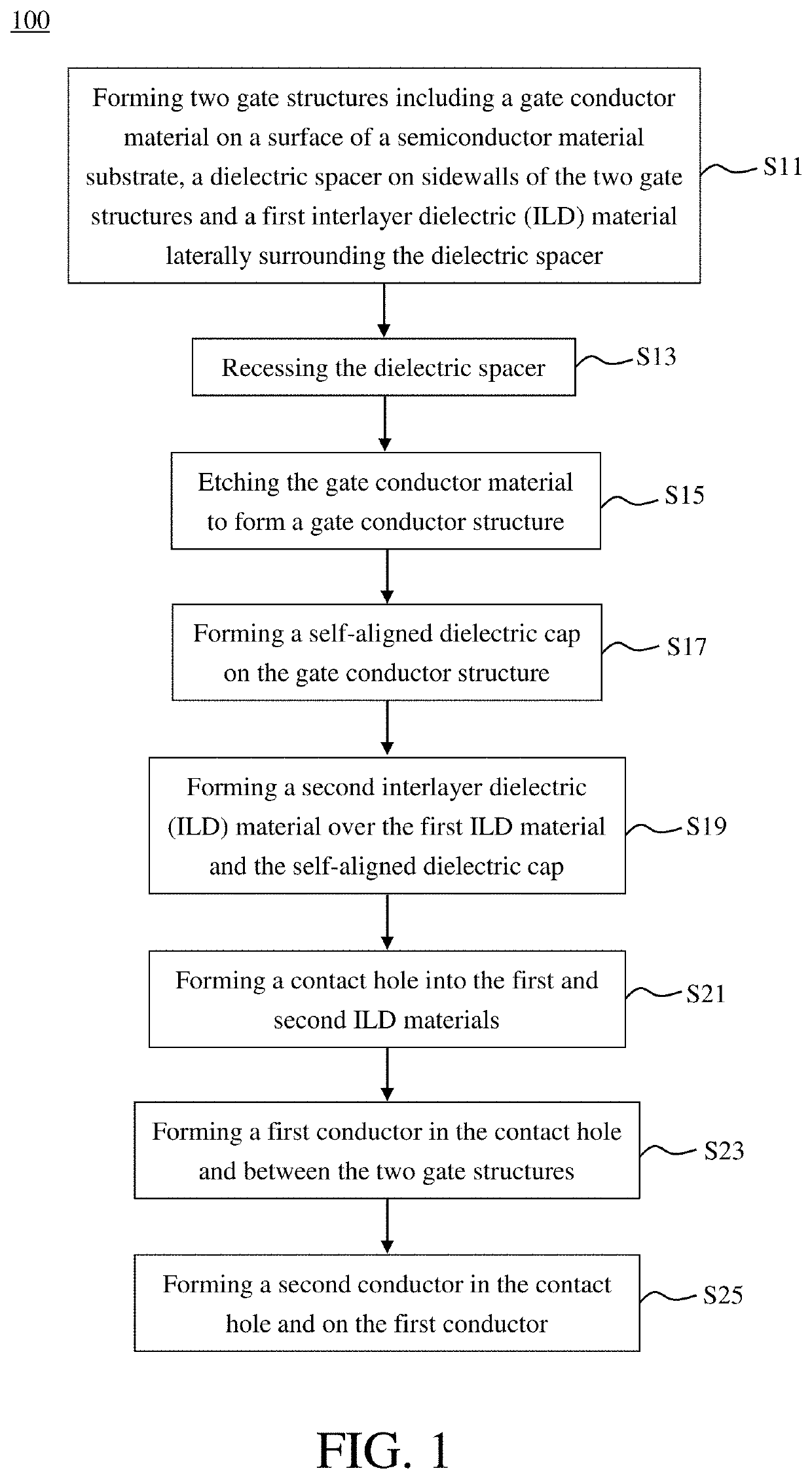
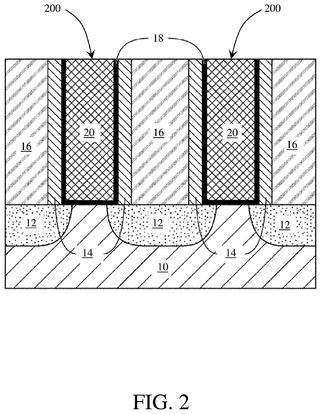
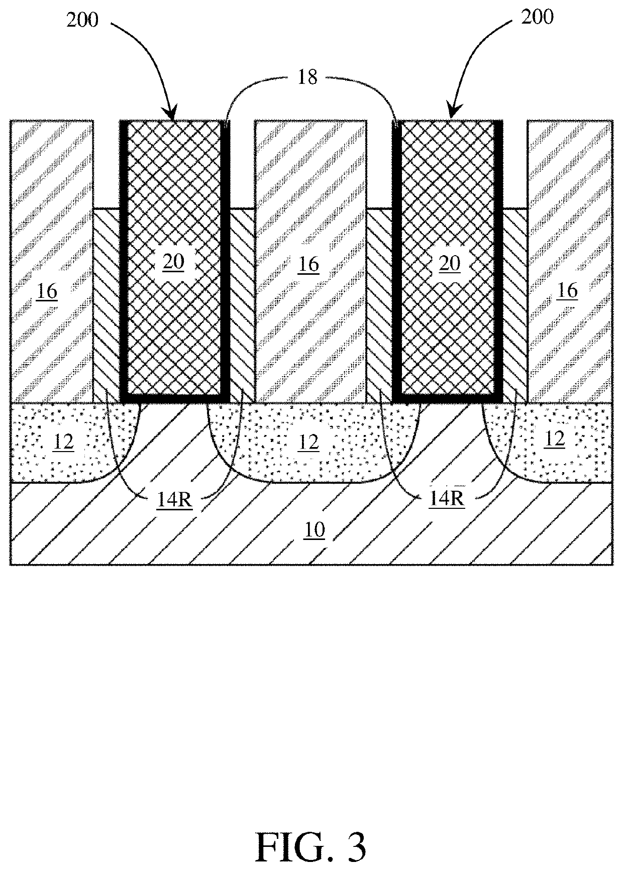
The present application discloses a semiconductor device and a method for fabricating the semiconductor device. The semiconductor device includes two gate structures, a first conductor, a barrier, a second conductor and a plurality of air gaps. The two gate structures are located on a surface of a semiconductor material substrate. The first conductor is disposed between the two gates structures. The barrier is disposed between the first conductor and the gate structure. The second conductor is disposed on the first conductor. The air gaps are disposed at two sides of the second conductor. A width of the second conductor is greater than a width of the first conductor.

Description

TECHNICAL FIELD[0001]The present disclosure relates to a semiconductor structure and a method of forming the same, and more particularly, to a semiconductor structure including at least one functional gate structure having reduced gate resistance and a self-aligned dielectric cap that is designed to increase process margin for self-aligned contact formation, and further a bit line is disposed above the self-aligned dielectric cap and electrically connected to a source-drain region through a bit line contact.DISCUSSION OF THE BACKGROUND[0002]The semiconductor industry has experienced rapid growth due to continuous improvements in the integration density of a variety of electronic components (e.g., transistors, diodes, resistors, capacitors, etc.). For the most part, this improvement in integration density has come from repeated reductions in minimum feature size (e.g., shrinking the semiconductor process node towards the sub-20 nm node), which allows more components to be integrated ...

Claims


Application Information

Patent Timeline
Patent Type & Authority Applications(United States)
IPC IPC(8): H01L21/768H01L23/535H01L29/06H01L29/423H01L29/417H01L29/78H01L29/786H01L21/02H01L29/66
CPCH01L21/76897H01L29/66742H01L29/0673H01L29/42392H01L29/41733H01L29/41791H01L29/7851H01L29/78696H01L21/02603H01L21/76805H01L21/7682H01L21/76895H01L29/66515H01L29/66795H01L23/535H01L21/76879H01L29/66545H01L29/6653H01L29/42376H01L21/76834H01L21/76844H01L2221/1063H01L23/485H01L29/775B82Y10/00
Inventor YANG, SHENG-HUI
Owner NAN YA TECH
Why Eureka
Try Eureka