
Ultrasound system and method for tracking movement of an object

a technology of ultrasonic and tracking movement, applied in the field of ultrasonic imaging, can solve the problems of reducing the accuracy or precision of detected positions, affecting the accuracy of object position tracking, and shifting the imaging field of view or imaging plane, so as to facilitate the improvement of object tracking accuracy, accurately locate the object position, and avoid compromising the accuracy of object movement tracking.

Pending Publication Date: 2022-03-03
KONINKLJIJKE PHILIPS NV
View PDF4 Cites 0 Cited by
  • Summary
  • Abstract
  • Description
  • Claims
  • Application Information

AI Technical Summary

Benefits of technology

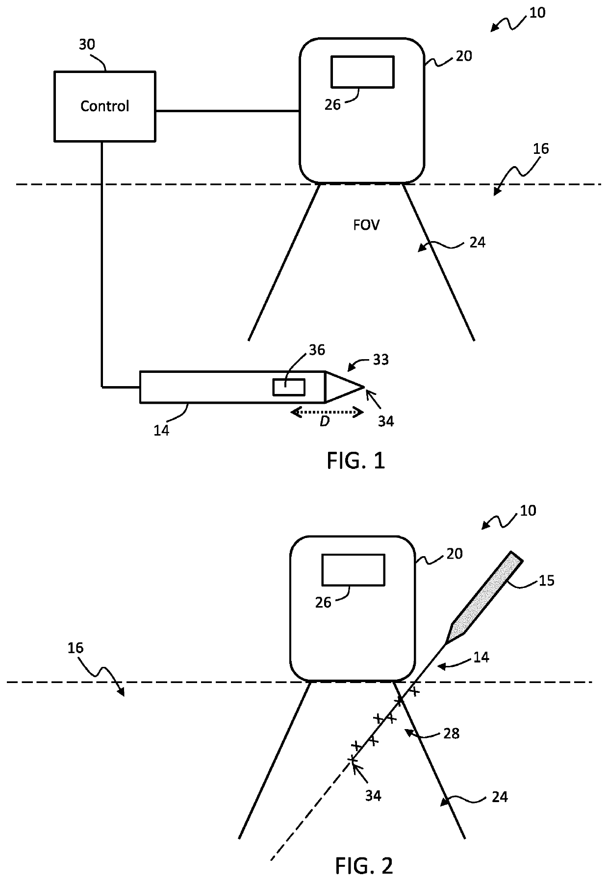
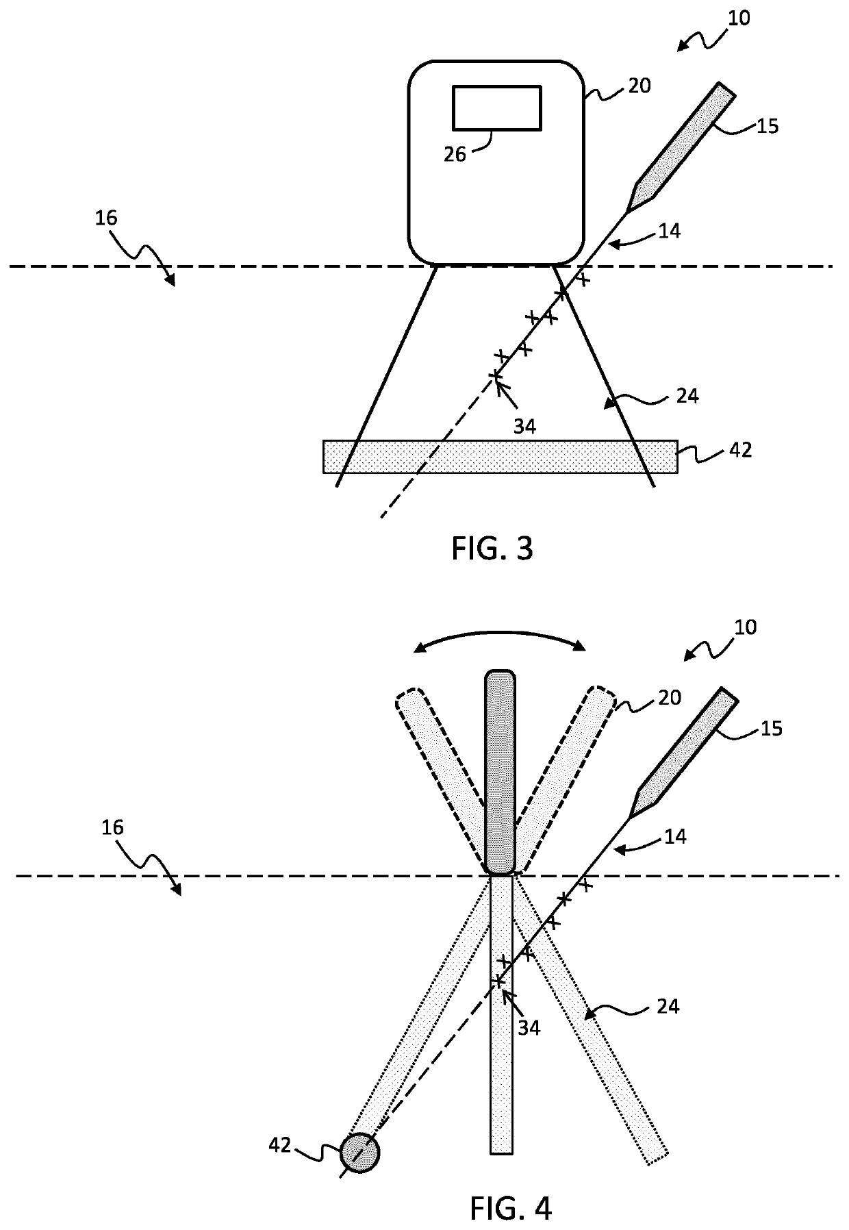
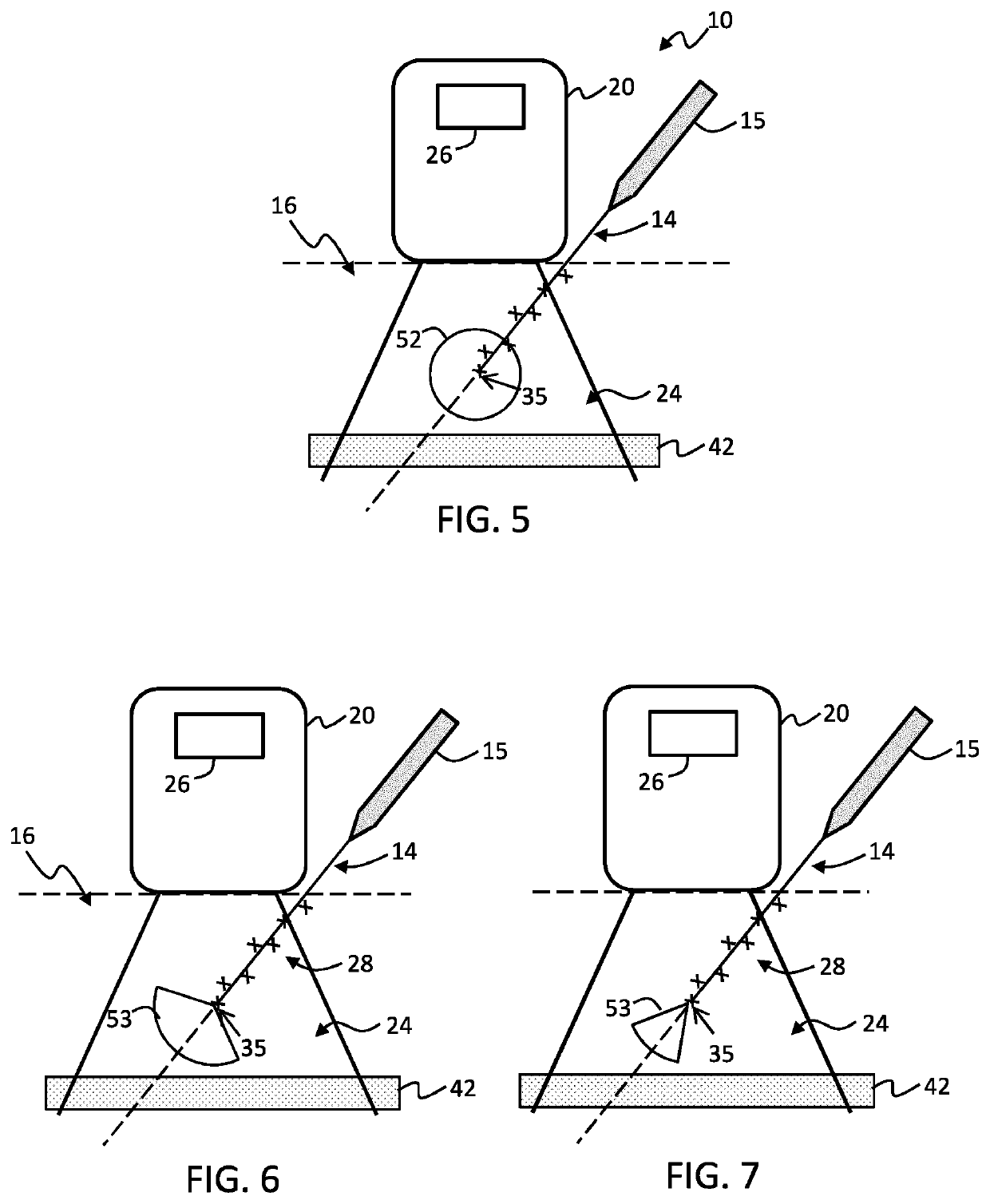
The present invention relates to a system and method for accurately tracking the position and direction of an object in a medical procedure. By using an ultrasound transducer to track the movement of the object, the system compensates for any changes in the field of view over time. This allows for more accurate tracking of the object without the need for additional sensors or increased size of the object being tracked. The system can track both in-plane and out-of-plane object movements, allowing for flexibility in tracking approach. The use of an ultrasound sensor allows for the accurate tracking of the position of the object within the body.

Problems solved by technology

A particular impediment with known ultrasound tracking procedures is that while the position of the object is continuously and accurately located in the displayed ultrasound image, the ultrasound probe itself may be rotated or translated with respect to the object, which leads to shifting of the imaging field of view (FOV) or imaging plane.
The shift of the field of view is largely indistinguishable from motion of the object itself in the medium being scanned, therefore leading to inaccuracy in the object position tracking.
However, this intermittent suppression of object tracking leads to reduced accuracy or precision in the detected positions.

Method used


Image

  • Ultrasound system and method for tracking movement of an object
  • Ultrasound system and method for tracking movement of an object
  • Ultrasound system and method for tracking movement of an object

Examples


Embodiment Construction

[0080]The invention will be described with reference to the Figures.

[0081]It should be understood that the detailed description and specific examples, while indicating exemplary embodiments of the apparatus, systems and methods, are intended for purposes of illustration only and are not intended to limit the scope of the invention. These and other features, aspects, and advantages of the apparatus, systems and methods of the present invention will become better understood from the following description, appended claims, and accompanying drawings. It should be understood that the Figures are merely schematic and are not drawn to scale. It should also be understood that the same reference numerals are used throughout the Figures to indicate the same or similar parts.

[0082]The invention provides a system and method for tracking an object received within a body using ultrasound wherein shifts in position of an ultrasound probe tracking the object (either deliberate or accidental) can be...


PUM


Abstract

A system and method for tracking an object (14) received within a body (16) using ultrasound wherein shifts in position of an ultrasound probe (20) tracking the object (either deliberate or accidental) can be corrected for. The method comprises tracking a position of the object through the body using an ultrasound transducer unit, and sensing movement of the ultrasound transducer unit using a physically coupled motion sensor (26). From the movement of the ultrasound transducer unit, movement of its field of view (24) can be determined. Based on a tracked history of positions (28) of the object through the field of view, and on the tracked movement of the field of view relative to the body, a direction of motion of the object through the body can be derived.

Description

FIELD OF THE INVENTION[0001]The present invention relates to the field of ultrasound imaging, and more specifically to the field of tracking an object, such as a tool, received within a body, using ultrasound.BACKGROUND OF THE INVENTION[0002]Precise visualization of objects, e.g. medical tools such as needles or catheters, received within a body is often required, for instance for certain minimally invasive interventions. Real-time localization of an object with respect to imaged anatomy is also often used.[0003]Ultrasound (US) imaging is one of the most popular imaging systems for tool guidance applications. Ultrasound imaging may be used to image tools such as needles, laparoscopes, stents, and radioactive seeds used for brachytherapy. For example, ultrasound imaging may be used for needle guidance in anesthesiology, tissue ablation or for biopsy guidance, since needles are used to take tissue samples, and to deliver medicine or electrical energy to the targeted tissue inside a pa...

Claims


Application Information

Patent Timeline
Patent Type & Authority Applications(United States)
IPC IPC(8): A61B34/20A61B8/08A61B8/00
CPCA61B34/20A61B8/0841A61B2034/2063A61B8/54A61B8/4254A61B8/5292A61B8/085A61B8/4245A61B17/3403A61B8/12A61B8/4477G06T7/246A61B2034/107A61B2034/2048A61B2090/378A61B2017/3413G06T2207/10132
Inventor VISSER, CORNELIS GERARDUSVEREL, IRISBANDARU, RAJA SEKHARSTEINBUCH, JEIRE
Owner KONINKLJIJKE PHILIPS NV
Learn More