

Laser forming non-square edges in transparent workpieces using modified airy beams
a technology of airy beams and transparent workpieces, applied in laser beam welding apparatus, welding/soldering/cutting articles, manufacturing tools, etc., can solve the problems of difficult use of rounded outer edges or like edges, complex mechanical processing of glass substrates, glass dust and glass particles
- Summary
- Abstract
- Description
- Claims
- Application Information
AI Technical Summary
Benefits of technology
Problems solved by technology
Method used
Image

Examples
example 1
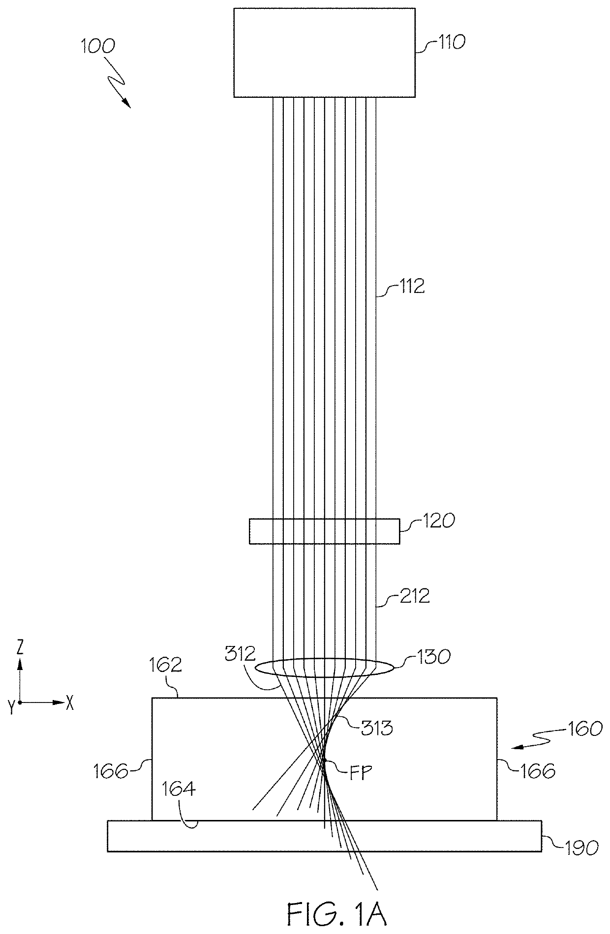
[0118]Example 1 is an example contour 170A of curved defects 172A formed using an Airy beam and an Airy beam focal region that is unmodified is depicted in FIGS. 6A and 6B. FIG. 6A is a top view of the example contour 170A of curved defects 172A formed in an example transparent workpiece 160 and FIG. 6B is a side view of a single curved defect 172A. To achieve the side view of FIG. 6B, the example transparent workpiece 160 was cleaved perpendicular to the contour 170A to provide a view of a single curved defect 172A. The Airy beam and the Airy beam focal region used to form the contour 170A of curved defects 172A was formed using the optical assembly 100 of FIG. 1A using a pulse burst Gaussian laser beam having a wavelength of 1064 nm, 2-20 sub-pulses per burst, a sub-pulse width of 10 ps, a time spacing of 10 ns-100 ns between consecutive sub-pulses in the burst, a repetition rate of 1 kHz, and a 200 μJ pulse burst energy. The unmodified Airy beam used to form Example 1 was formed ...
example 2
[0119]Example 2 is an example contour 170B of curved defects 172B is depicted in FIGS. 7A and 7B that is formed using an elliptical Airy beam and an elliptical Airy beam focal region generated using an elliptical Gaussian laser beam. FIG. 7A is a top view of the example contour 170B of curved defects 172B formed in an example transparent workpiece 160 and FIG. 7B is a side view of a single curved defect 172B. To achieve the side view of FIG. 7B, the example transparent workpiece 160 was cleaved perpendicular to the contour 170B to provide a view of a single curved defect 172B. The Airy beam and the Airy beam focal region used to form the contour 170A of curved defects 172A was formed using the optical assembly 100″ of FIG. 4A using a pulse burst Gaussian laser beam having a wavelength of 1064 nm, 2-20 sub-pulses per burst, a sub-pulse width of 10 ps, a time spacing of 10 ns-100 ns between consecutive sub-pulses in the burst, a repetition rate of 1 kHz, and a 200 μJ pulse burst energ...
example 3
[0121]Example 3 is an example non-square edge 168A (a so-called bullnose edge) as shown in FIGS. 8A and 8B. FIG. 8A is a side view of the example non-square edge 168A comprising a bullnose shape formed in an example transparent workpiece 160 of non-ion exchanged Corning Gorilla® Glass with a thickness of 200 μm. FIG. 8B is a front view of the example non-square edge 168A. The example non-square edge 168A was formed in the example transparent workpiece 160 using the optical assembly 100″ of FIG. 4A to form an elliptical Airy beam. The elliptical Airy beam is a pulsed beam comprising 300 μJ pulse bursts having 9 sub-pulses with a sub-pulse separation of 12.5 ns between each sub pulse and a burst duration of 720 ns. The pulse bursts used in Example 3 were repeated with a repetition rate of 200 kHz. During the laser processing of Example 3, the example transparent workpiece 160 was translated relative to the elliptical Airy beam such that the pitch of adjacent pulse bursts impinging the...
PUM
| Property | Measurement | Unit |
|---|---|---|
| Fraction | aaaaa | aaaaa |
| Fraction | aaaaa | aaaaa |
| Transparency | aaaaa | aaaaa |
Abstract
Description
Claims
Application Information