
Charged Particle Beam Device

a charge-pulverized particle and beam technology, applied in the direction of electric discharge tubes, basic electric elements, electrical equipment, etc., can solve the problem of changing the convergence angle of the electron beam

Active Publication Date: 2022-03-17
JEOL LTD
View PDF6 Cites 0 Cited by
  • Summary
  • Abstract
  • Description
  • Claims
  • Application Information

AI Technical Summary

Benefits of technology

This patent is for a charged particle beam device that includes a source, a blanking device, an optical system, and a control unit. The control unit is responsible for setting a target value for the dose of the charged particle beam and the ratio of time during which the charged particle beam is not blocked to a unit time. Based on this information, the electrostatic deflector operates to block / unblock the charged particle beam. The technical effect of this invention is to provide a device for precise and safe irradiation of a specimen with a charged particle beam.

Problems solved by technology

Furthermore, resizing of the aperture causes a convergence angle of the electron beam to change.

Method used


Image

  • Charged Particle Beam Device
  • Charged Particle Beam Device
  • Charged Particle Beam Device

Examples


first embodiment

1. First Embodiment

1.1. Electron Microscope

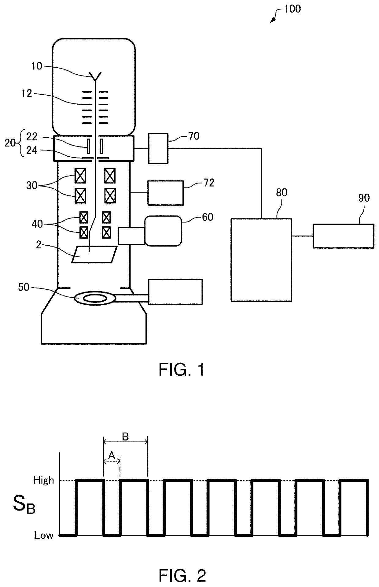
[0049]First, an electron microscope according to the first embodiment will be described with reference to the drawings. FIG. 1 is a diagram illustrating a configuration of an electron microscope 100 according to the first embodiment.

[0050]The electron microscope 100 is a scanning transmission electron microscope (STEM) for scanning a specimen 2 with an electron beam (an example of a charged particle beam) and detecting electrons having been transmitted through the specimen 2 to obtain a scanned image.

[0051]A scanned image is an image obtained by scanning with a charged particle beam such as an electron beam or an ion beam. Scanned images include bright-field STEM images, dark-field STEM images including HAADF images, EDS maps using an energy-dispersive X-ray spectrometer (EDS), and EELS maps using an electron energy-loss spectrometer (EELS).

[0052]As illustrated in FIG. 1, the electron microscope 100 includes an electron source 10 (an exampl...

second embodiment

2. Second Embodiment

2.1. Electron Microscope

[0145]Next, an electron microscope according to the second embodiment will be described with reference to the drawings. FIG. 20 is a diagram illustrating a configuration of an electron microscope 200 according to the second embodiment. Hereinafter, in the electron microscope 200 according to the second embodiment, members having similar functions to the components of the electron microscope 100 according to the first embodiment will be denoted by same reference characters and a detailed description thereof will be omitted.

[0146]The electron microscope 100 according to the first embodiment is a scanning transmission electron microscope (STEM) for scanning a specimen 2 with an electron beam and acquiring a scanned image.

[0147]By comparison, the electron microscope 200 according to the second embodiment is a transmission electron microscope (TEM) for imaging a specimen image using electrons having been transmitted through a specimen 2. The el...


PUM


Abstract

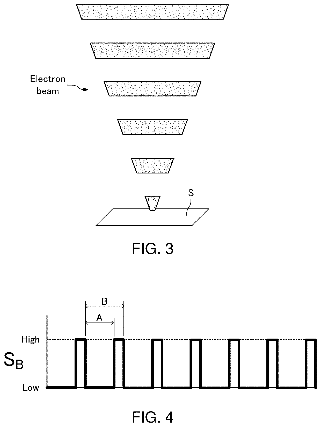
A charged particle beam device including: a charged particle beam source which emits a charged particle beam; a blanking device which has an electrostatic deflector that deflects and blocks the charged particle beam; an irradiation optical system which irradiates a specimen with the charged particle beam; and a control unit which controls the electrostatic deflector, the control unit performing processing of: acquiring a target value of a dose of the charged particle beam for the specimen; setting a ratio A / B of a time A during which the charged particle beam is not blocked to a unit time B (where A≠B, A≠0), based on the target value; and operating the electrostatic deflector based on the ratio.

Description

CROSS-REFERENCE TO RELATED APPLICATION[0001]This application claims priority to Japanese Patent Application No. 2020-156305 filed Sep. 17, 2020, the disclosure of which is hereby incorporated by reference in its entirety.BACKGROUND OF THE INVENTIONField of the Invention[0002]The present invention relates to a charged particle beam device.Description of Related Art[0003]Charged particle beam devices such as a transmission electron microscope, a scanning transmission electron microscope, a scanning electron microscope, and a focused ion-beam device are provided with an irradiation optical system for irradiating a specimen with an electron beam, an ion beam, or the like. The irradiation optical system includes a condenser lens, an aperture, and an aberration corrector such as a Cs corrector.[0004]For example, JP-A-2019-129073 discloses an electron microscope provided with an irradiation optical system that includes an aberration corrector for correcting spherical aberration and chromat...

Claims


Application Information

Patent Timeline
Patent Type & Authority Applications(United States)
IPC IPC(8): H01J37/28H01J37/04H01J37/147H01J37/244
CPCH01J37/28H01J37/045H01J2237/24415H01J37/244H01J37/1477H01J37/26H01J37/268H01J37/265H01J2237/24455H01J2237/2802
Inventor YAGI, KAZUKIJIMBO, YUREED, BRYAN W.BLOOM, RUTH SHEWMON
Owner JEOL LTD
Learn More