
Millimeter-wave scalable pll-coupled array for phased-array applications

a technology of phased arrays and millimeterwaves, applied in the direction of pulse automatic control, electrical equipment, antennas, etc., can solve the problems of high power loss/consumption caused by phase shifters at sub-thz frequencies, increase in power consumption and hence system cost,

Active Publication Date: 2022-04-07
RGT UNIV OF CALIFORNIA
View PDF20 Cites 5 Cited by
  • Summary
  • Abstract
  • Description
  • Claims
  • Application Information

AI Technical Summary

Benefits of technology

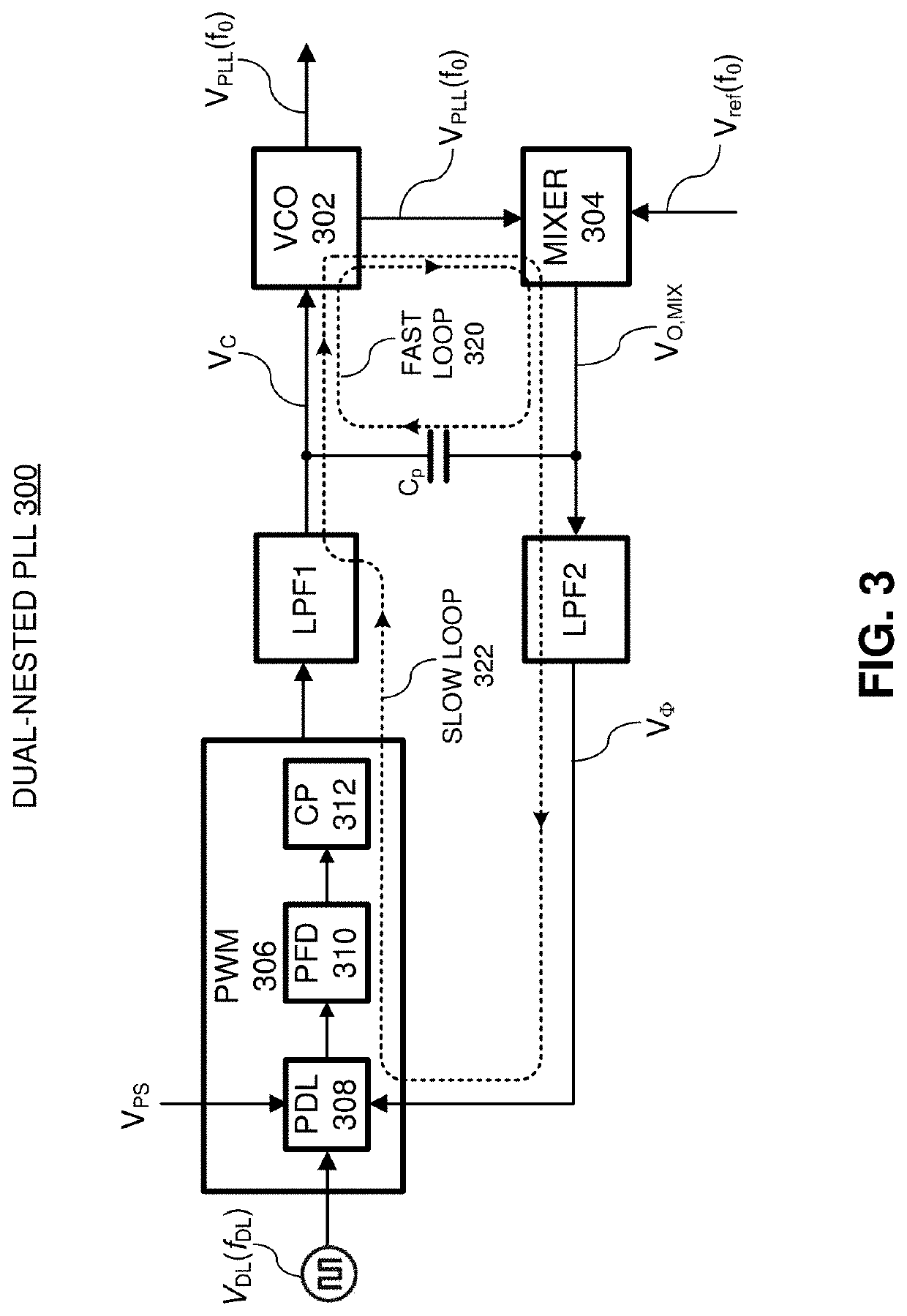
The patent describes various techniques for generating desired phase shifts in a phased array to control the directions of radiation in a wide range of angles. The proposed architecture uses novel PLL-coupled phase shifting techniques for implementation in millimeter-wave and sub-terahertz operations, which eliminates the use of conventional lossy phase shifters and reduces power loss and power consumption. The slow loop includes adjustable delay circuitry that generates the phase shift, and the mixer is designed to have a symmetrical topology for receiving differential signals from both the local and adjacent VCOs, which avoids long signal routings to the mixer at high operating frequencies. The PLL-coupled architecture includes a chain of continuously-coupled PLLs, wherein each PLL includes a local VCO and control circuitry that controls a phase shift between the local and adjacent local VCOs to facilitate phased-array operations. The technical effects of this patent include reducing power loss and power consumption in the phased array, making it suitable for larger applications, and avoiding long signal routings to the mixer at high operating frequencies.

Problems solved by technology

Despite the proven advantages, designing phased arrays for mm-wave / sub-THz frequencies is a challenging task.
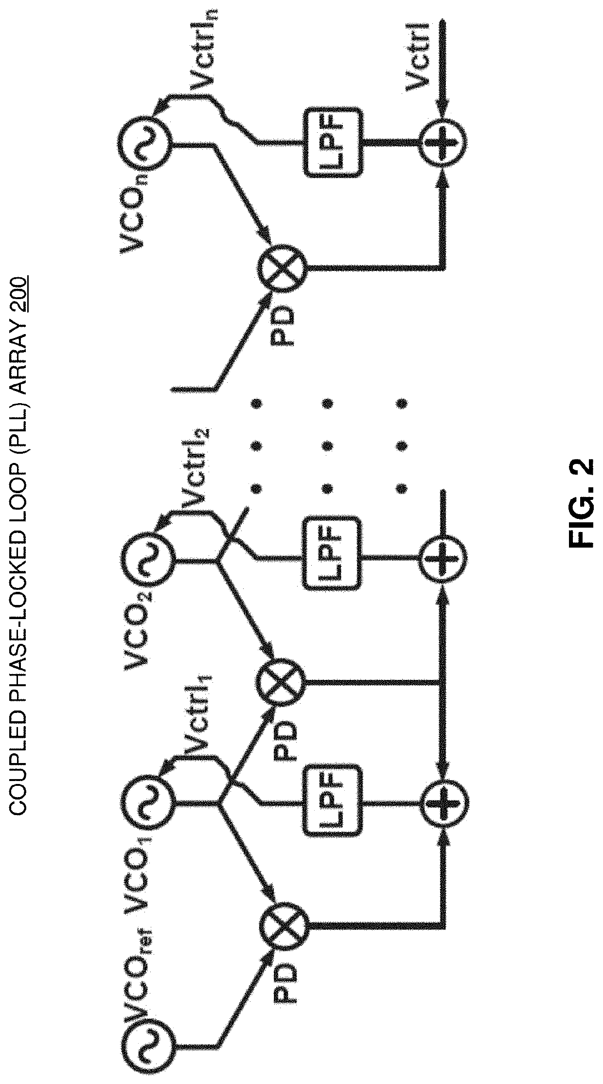
However, these coupling-based and injection-based techniques complicate the phased array design and hinder the scaling of the multi-antenna structure, causing an increase in power consumption and hence cost of the system.
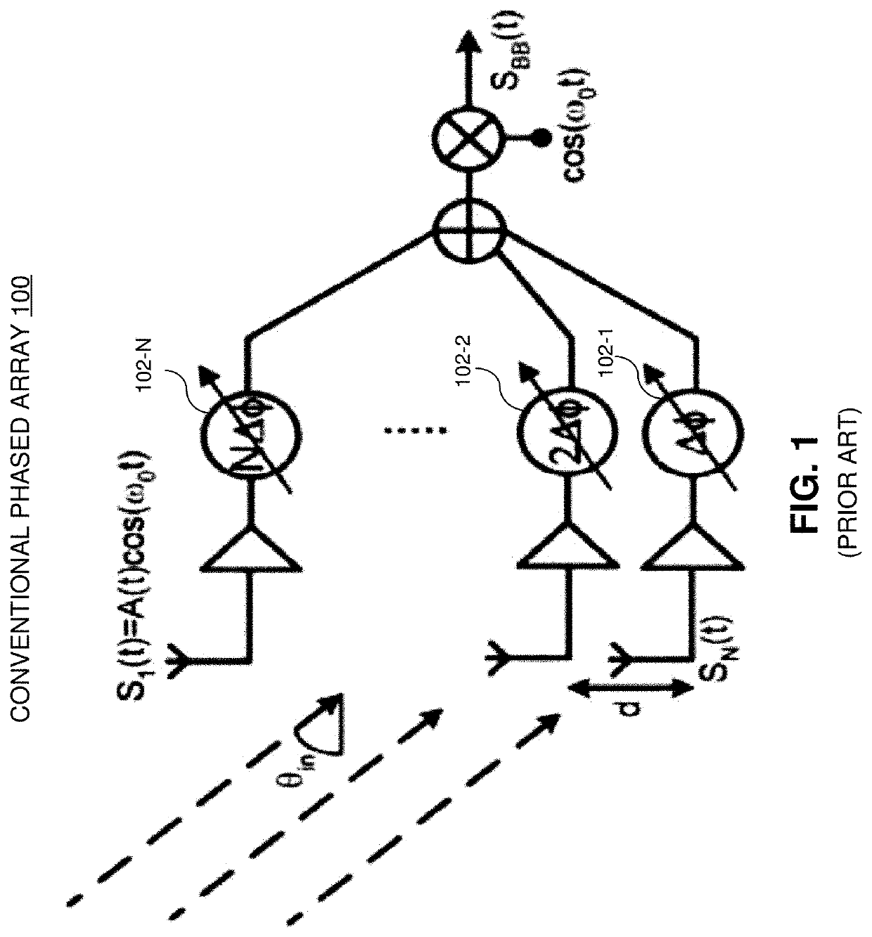
Another design challenge in phased array systems is related to the high power loss / consumption caused by phase shifters at sub-THz frequencies. FIG. 1 shows a conventional phase array 100 which employs phase shifters to achieve the desired phase shift between adjacent radiating elements.
However, each of these three types of phase shifting architecture is associated with issues and challenges.
RF and LO phase shifting architectures typically require the design of phase shifters at high frequencies, which increases both power consumption and loss.
RF phase shifters also require power dividers / combiners which further add to the power consumption and the loss.
In LO phase shifting architecture, coherent distribution of multiple phases to multiple front-ends has proven to be a challenging task.
However, the area / size of the IF phase shifters becomes much larger, and the required mirror frequency rejection becomes a serious problem.
In addition, increased inter-symbol interference (ISI) can deteriorate the system performance in IF phase shifters.
However, solutions involving injection-locked or coupled oscillators are generally bandwidth-limited.
Nonetheless, frequency multiplication adds to the complexity and essentially suffers from poor power efficiency, thus further increasing the overall power consumption.
The mismatch between the simulation and measurement due to fabrication errors can result in the fluctuation in frequency and amplitude of the oscillators and leads to phase and beam-steering errors.
This up-scaling of a phased array would not be possible with conventional phase shifters because the power consumption would significantly limit the achievable power gain.

Method used


Image

  • Millimeter-wave scalable pll-coupled array for phased-array applications
  • Millimeter-wave scalable pll-coupled array for phased-array applications
  • Millimeter-wave scalable pll-coupled array for phased-array applications

Examples


Embodiment Construction

[0061]The following description is presented to enable any person skilled in the art to make and use the disclosed embodiments, and is provided in the context of one or more particular applications and their requirements. Various modifications to the disclosed embodiments will be readily apparent to those skilled in the art, and the general principles defined herein may be applied to other embodiments and applications without departing from the scope of those that are disclosed. Thus, the present invention or inventions are not intended to be limited to the embodiments shown, but rather are to be accorded the widest scope consistent with the disclosure.

[0062]This disclosure provides various techniques, systems and architectures for generating desired phase shifts in a phased array to control the directions of radiation in a wide range of angles. Particularly, phased array architectures based on novel phase-locked-loop-coupled (PLL-coupled) phase shifting techniques for implementatio...


PUM


Abstract

Techniques, systems and architectures for generating desired phase shifts in a phased array to control the directions of radiation in a wide range of angles are disclosed. Particularly, phased array architectures based on novel PLL-coupled phase shifting techniques for implementation in millimeter-wave (mm-wave) and sub-terahertz (sub-THz) operations range are described. In one aspect, a phased array including an array of unit cells is disclosed. In some embodiments, each unit cell in the array of unit cells includes a dual-nested PLL that is configured to effectuate phase locking and frequency locking to a reference signal from an adjacent unit cell. Moreover, each PLL includes control circuitry that can generate a wide range of phase shifts between adjacent unit cells to facilitate phased-array operations. Note that using the dual-nested PLL to generate a desired phase shift between adjacent radiating elements eliminates the use of conventional lossy phase shifters in the phased array.

Description

CROSS-REFERENCE TO RELATED APPLICATION[0001]This application claims the benefit of priority under 35 U.S.C. 119(e) to U.S. Provisional Patent Application Ser. No. 63 / 088,884, entitled “mm-Wave Scalable PLL-Coupled Array for Phased-Array Applications in 65-nm CMOS,” Attorney Docket Number UC21-635-1PSP, filed on 7 Oct. 2020, the contents of which are incorporated by reference herein.GOVERNMENT LICENSE RIGHTS[0002]This invention was made with U.S. government support under grant number 1408628 awarded by the National Science Foundation (NSF). The U.S. government has certain rights in the invention.BACKGROUNDField[0003]The disclosed embodiments generally relate to the design of phased arrays. More specifically, the disclosed embodiments relate to the design of a highly stable, highly scalable phased array which utilizes a dual-nested loop PLL to generate the phase shift in place of conventional phase shifters.Related Art[0004]Fully-integrated silicon-based millimeter-wavelength (mm-wave...

Claims


Application Information

Patent Timeline
Patent Type & Authority Applications(United States)
IPC IPC(8): H01Q3/36H01Q21/00
CPCH01Q3/36H01Q21/0006H01Q3/34H03L7/0802
Inventor AFZAL, HAMIDREZAMOMENI, OMEEDKANANIZADEH, ROUZBEHABEDI, RAZIEHHEYDARI, PAYAM
Owner RGT UNIV OF CALIFORNIA
Learn More