
High voltage battery module with series connected cells and internal relays

a battery module and series connection technology, applied in secondary cells, battery components, battery servicing/maintenance, etc., can solve the problems of high power level, fire or explosion, short circuit in the pack, etc., to minimize the risk of fire and energy loss in operation, the effect of safe handling

Active Publication Date: 2022-05-05
PALATOV GRP LLC
View PDF0 Cites 0 Cited by
  • Summary
  • Abstract
  • Description
  • Claims
  • Application Information

AI Technical Summary

Benefits of technology

The present invention provides a high voltage battery module for vehicles that is safe to handle and transport without specialized training or equipment. The module has a modular pack design that allows for fault tolerance, rapid replacement of failed or discharged modules, and minimizes risks of hazard in case of adverse events. The cells in the module are connected in series, which prevents an internal short due to dendrite growth from creating a hazardous condition or thermal runaway.

Problems solved by technology

Such levels of power can present many life-threatening hazards both during ordinary assembly and service operations, as well as rescue operations by emergency personnel when electric vehicles are involved in a crash or other adverse event.
Exposure to moisture through condensation, precipitation, or accidental submersion can cause a short in the pack and lead to a fire or explosion.
Because a large number of cells is typically needed, resulting in substantial weight and bulk, vehicle battery packs are often constructed of modules.
While this may be practical in mainstream automotive applications, in high performance vehicles which see severe use as part of ordinary operation, this approach is undesirable.
This characteristic makes it impractical to add relays to each module, due to expense of high-current relays and increased resistance that would add up when multiple modules are connected in series.
With large current capability, a short across the external terminals can result in very large amount of energy being released and carries a high risk of fire, serious injury, as well as potential damage to the module.
Hom does not contemplate the safe handling of individual batteries, and therefore does not anticipate isolating both external terminals from the cells within a battery.
A further drawback of module or pack construction that utilizes groups of cells connected in parallel is the fact that if one cell in such group develops an internal short, which is a known failure mode resulting from dendrite growth, the full current of all the other cells in the group will flow through the failed cell.
This can lead to rapid overheating and a resulting explosion or fire.
A key drawback of this approach is that in ordinary use the inherent resistance of the fusible links leads to unwanted heat generation and overall energy loss in the pack when operating at high current levels.
Another undesirable effect of a plurality of cells connected in parallel within a module is that if one of the cells develops excessive self-discharge, which is a known defect, then all the cells in parallel with it will discharge through the defective cell over time.
Over-discharging the lowest group will lead to permanent damage of the group and therefore the entire pack.
In this way, a single defective cell in a pack constructed according to methods currently practiced in the art can result in effectively degrading the capacity of the entire pack.
Servicing such packs is hazardous and requires specialized training and equipment and is usually not practical.
Vehicle battery packs known in the art are extremely hazardous when opened for service or compromised in a crash or other adverse event.
Such vehicles see extreme use in ordinary operation, involving frequent crashes and requiring extensive service.
Therefore, the designs and priorities employed in construction of mainstream automotive battery packs are not practical in such applications.

Method used


Image

  • High voltage battery module with series connected cells and internal relays
  • High voltage battery module with series connected cells and internal relays
  • High voltage battery module with series connected cells and internal relays

Examples


Embodiment Construction

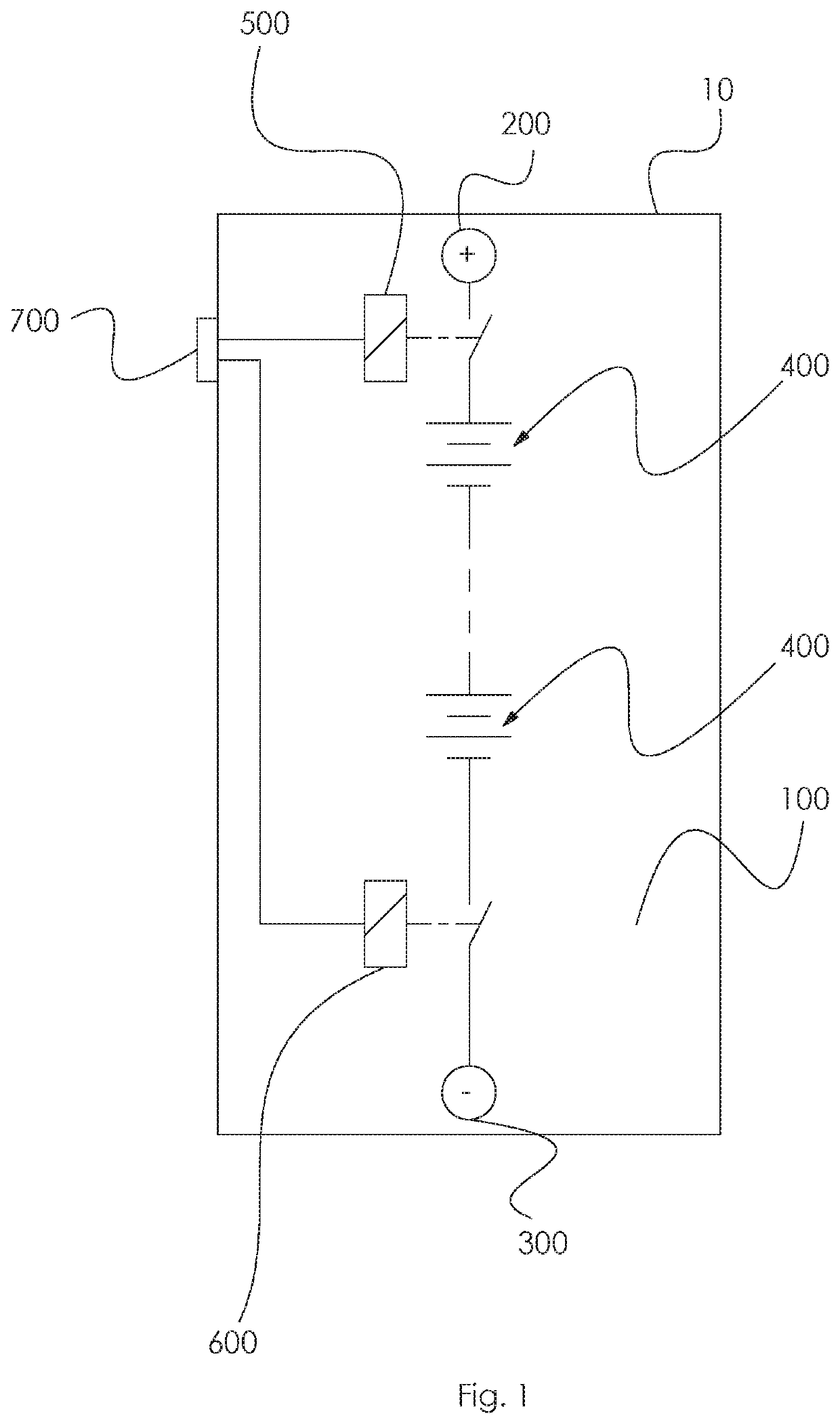
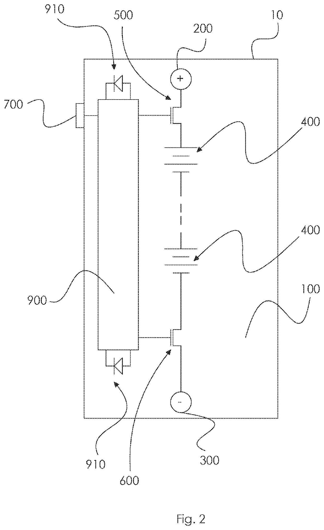
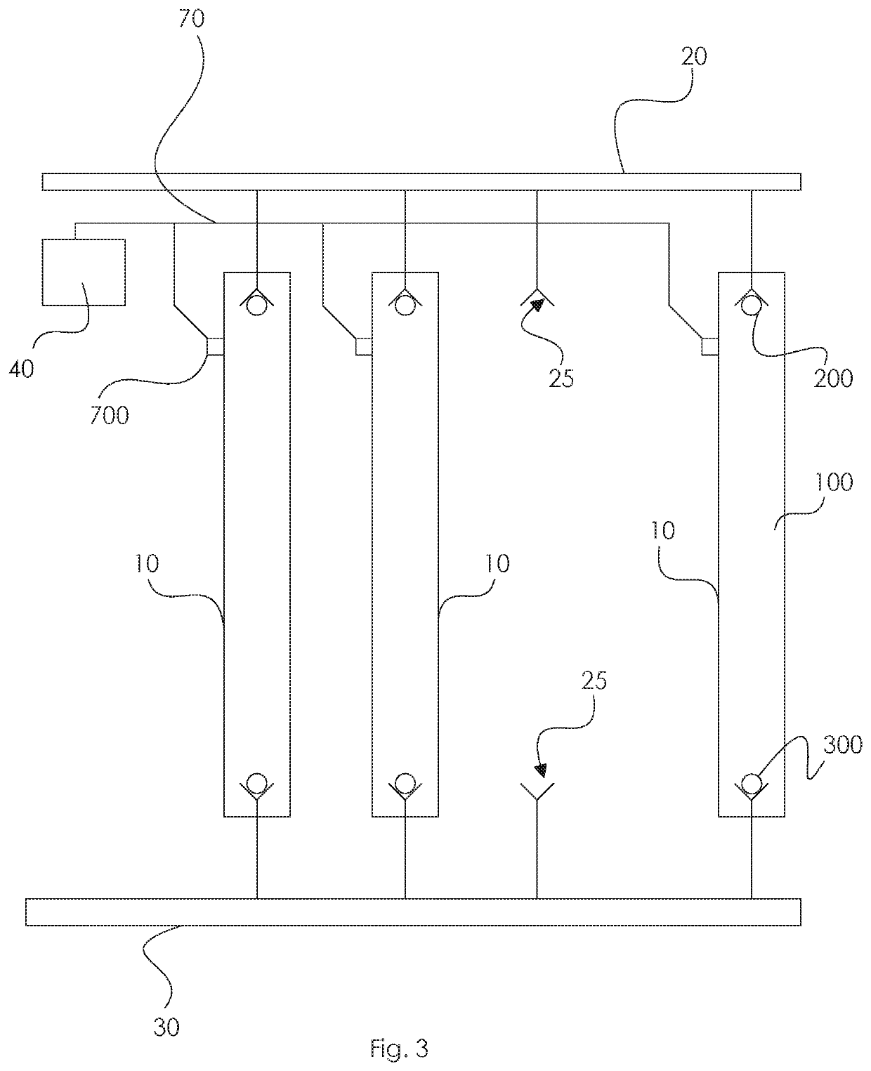
[0029]An embodiment of the present invention is illustrated in FIG. 1 is the most basic embodiment of the invention. The battery module 10 comprises an enclosure 100, a plurality of series connected cells 400, a positive terminal 200, and a negative terminal 300. In default configuration, all the said components are electrically isolated from all others, no voltage potential exists on the exterior of the pack, and no current can flow if any of said components are connected by an external electrical short.

[0030]The disclosed systems and methods for securing a battery module 10 will become better understood through review of the following detailed description in conjunction with the figures. The detailed description and figures provide examples of the various inventions described herein. Those skilled in the art will understand that the disclosed examples may be varied, modified, and altered without departing from the scope of the inventions described herein. Many variations are conte...


PUM

PropertyMeasurementUnit
currentaaaaaaaaaa
voltageaaaaaaaaaa
voltageaaaaaaaaaa

Abstract

A battery module is disclosed having a plurality of series-connected battery cells contained in, and electrically isolated from, an enclosure, with a first internal relay to control connection between cells and a positive terminal, and a second internal relay to control the connection between cells and a negative terminal. A control signal input is provided to control the relays. An embodiment is disclosed having an internal battery management system which controls the relays in response to a digital message. A modular battery pack is disclosed consisting of a plurality of modules connected in parallel, which can be individually and independently activated and deactivated. A method is provided for activating an individual module.

Description

BACKGROUND OF THE INVENTION[0001]There is a rapidly growing demand for converting a wide variety of vehicle types to electric propulsion. In order to deliver the best performance and efficiency, the electric drivetrains of such vehicles need to operate at a direct current (DC) high voltage. Systems operating at a nominal 400V DC are now common, and higher performance designs using 800V DC and above are being put into service.[0002]The battery packs to power such systems are increasing in capacity. Packs of over 70 KWh are now common, and some can deliver over 2,000 A of current. Such levels of power can present many life-threatening hazards both during ordinary assembly and service operations, as well as rescue operations by emergency personnel when electric vehicles are involved in a crash or other adverse event.[0003]Exposure to moisture through condensation, precipitation, or accidental submersion can cause a short in the pack and lead to a fire or explosion.[0004]Large capacity ...

Claims


Application Information

Patent Timeline
Patent Type & Authority Applications(United States)
IPC IPC(8): H01M10/42H01M2/20
CPCH01M10/4257H01M2/206H01M2220/20H01M2010/4278H01M2010/4271H01M50/51H01M50/249Y02E60/10B60L50/64H01M50/502
Inventor PALATOV, DENNIS
Owner PALATOV GRP LLC
Learn More