X-ray reference object, x-ray detector, additive manufacturing apparatus and method for calibrating the same

a technology of x-ray reference object and x-ray detector, which is applied in the direction of additive manufacturing, manufacturing tools, and process efficiency improvement, can solve the problems of poor three-dimensional article quality, poor calibration accuracy, and incorrect position of electron beam, so as to improve the control and performance of electron beams, improve calibration accuracy, and facilitate use

Inactive Publication Date: 2022-05-12
ARCAM AB
View PDF2 Cites 0 Cited by
  • Summary
  • Abstract
  • Description
  • Claims
  • Application Information

AI Technical Summary

Benefits of technology

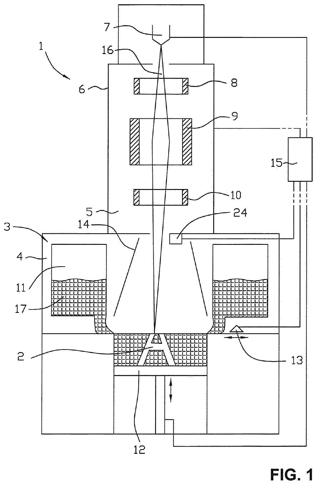
[0011]The present invention aims at obviating the aforementioned disadvantages and failings of previously known apparatus / machines for additive manufacturing of a three-dimensional article, and at providing an improved apparatus, which machine exhibits improved electron beam control and performance compared to conventional machines due to improved calibration accuracy in production-like circumstances. A primary object of the present invention is to provide a new calibration technique for calibrating an electron beam unit of an additive manufacturing apparatus, wherein the new calibration technique is accurate and easy to use.

Problems solved by technology

However, due to electromagnetic disturbances from the environment, physical vibration of the additive manufacturing apparatus, non-ideal components in the electron beam unit, etc. the electron beam spot risk having deficient / imperfect shape, size and / or position resulting in a poor-quality three-dimensional article.
It is also a risk that the magnetic field from the electromagnetic focus coil may interact with the astigmatism coil and / or the deflection coil, which results in interference or cross-talk between these coils, resulting in incorrect electron beam position, shape or size and thus a poor-quality three-dimensional article.
However, when increasing the energy content of the electron beam the thin cross risks becoming distorted / damaged, i.e. jeopardizing the entire calibration / adjustment.

Method used


Image

  • X-ray reference object, x-ray detector, additive manufacturing apparatus and method for calibrating the same
  • X-ray reference object, x-ray detector, additive manufacturing apparatus and method for calibrating the same
  • X-ray reference object, x-ray detector, additive manufacturing apparatus and method for calibrating the same

Examples


Embodiment Construction

[0041]Various embodiments of the present invention will now be described more fully hereinafter with reference to the accompanying drawings, in which some, but not all embodiments of the invention are shown. Indeed, embodiments of the invention may be embodied in many different forms and should not be construed as limited to the embodiments set forth herein. Rather, these embodiments are provided so that this disclosure will satisfy applicable legal requirements. Unless otherwise defined, all technical and scientific terms used herein have the same meaning as commonly known and understood by one of ordinary skill in the art to which the invention relates. The term “or” is used herein in both the alternative and conjunctive sense, unless otherwise indicated. Like numbers refer to like elements throughout.

[0042]Still further, to facilitate the understanding of this invention, a number of terms are defined below. Terms defined herein have meanings as commonly understood by a person of ...


PUM

PropertyMeasurementUnit
diameteraaaaaaaaaa
diameteraaaaaaaaaa
center-to-center distanceaaaaaaaaaa

Abstract

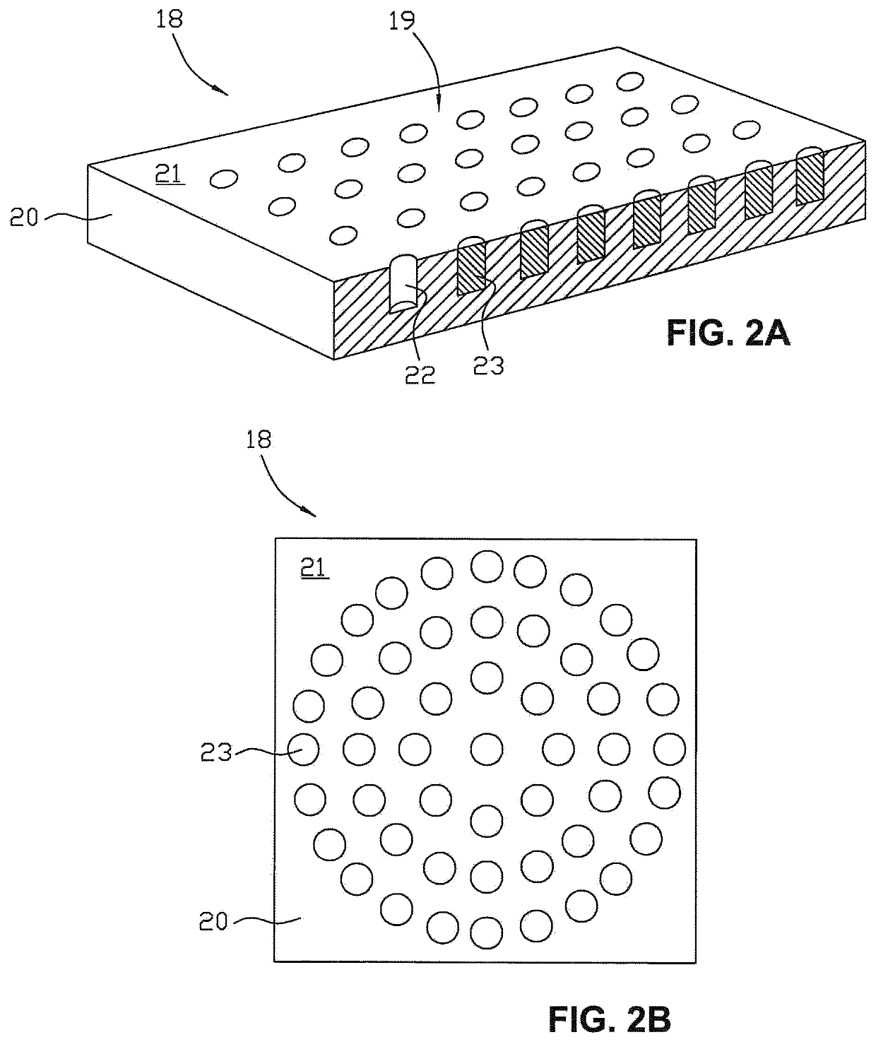
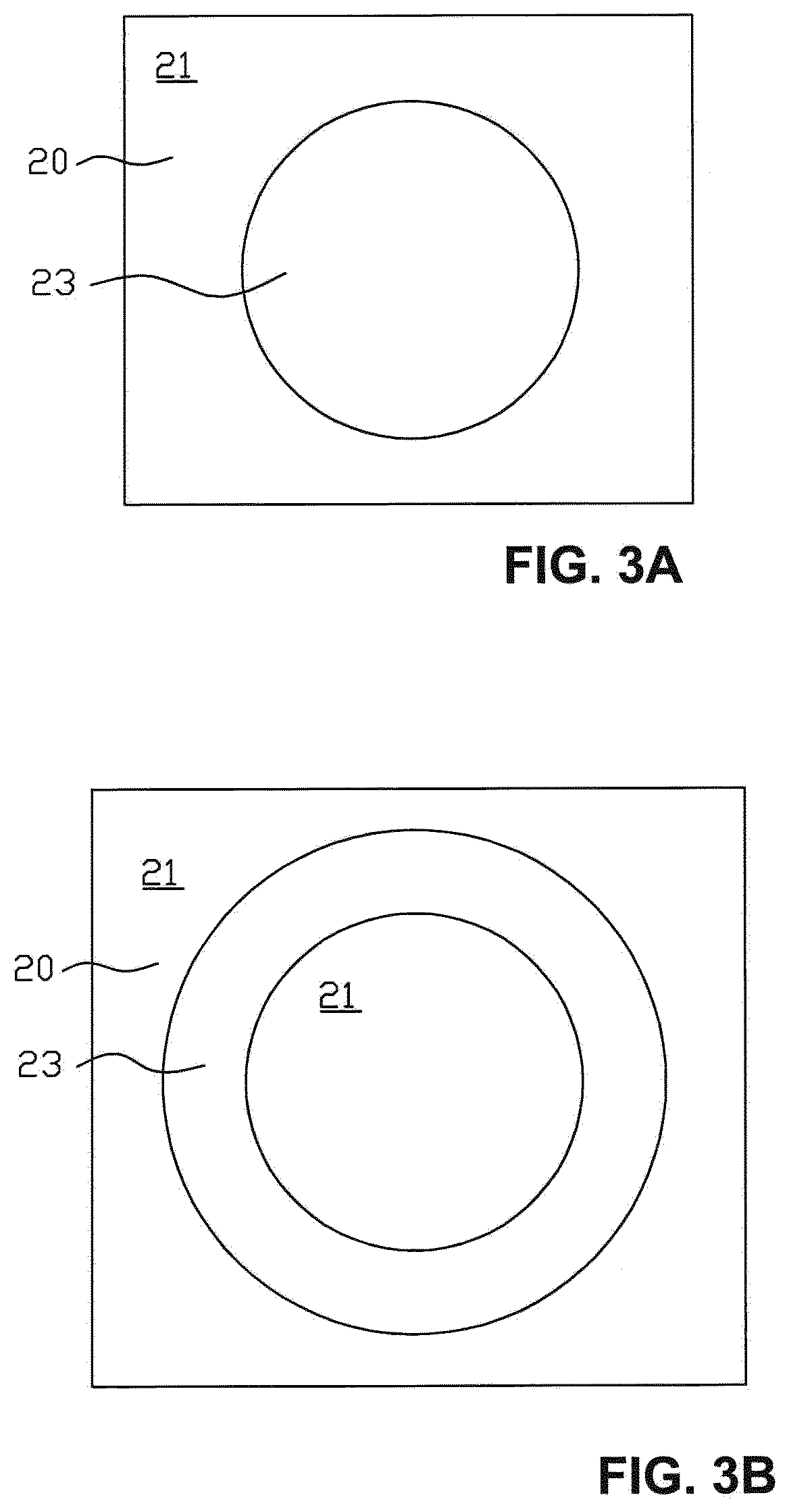
The present specification relates to an additive manufacturing apparatus comprising an X-ray reference object (18) for calibrating an electron beam unit in the additive manufacturing apparatus by detecting X-rays generated by sweeping an electron beam from the electron beam unit over a reference surface (19) of the X-ray reference object (18) and processing the detected signals, the X-ray reference object (18) comprising a support body (20) that has a top surface (21) and comprises a plurality of holes (22) in the top surface (21), The X-ray reference object (18) comprises a plurality of target members (23) inserted into the plurality of holes (22) of the support body (20). The present specification also relates to an X-ray detector to be used in the additive manufacturing apparatus, and to a method for calibrating such an additive manufacturing apparatus.

Description

CROSS REFERENCE TO RELATED APPLICATIONS[0001]This specification is a National Phase Entry of International Application No. PCT / EP2019 / 055166 filed Mar. 1, 2019 and entitled “X-RAY REFERENCE OBJECT, X-RAY DETECTOR, ADDITIVE MANUFACTURING APPARATUS AND METHOD FOR CALIBRATING THE SAME” which itself claims priority to and the benefit of U.S. Provisional Patent Application No. 62 / 782,897, filed on Dec. 20, 2018, and U.S. Provisional Patent Application No. 62 / 801,493, filed on Feb. 5, 2019; the contents of each of which are hereby incorporated by reference in their entirety.BACKGROUNDRelated Field[0002]The present invention relates generally to the field of apparatus and methods for additive manufacturing of a three-dimensional article by successively fusing layer by layer of powder material by means of an electron beam, e.g. Electron Beam Melting (EBM) machines. Further, the present invention relates particularly to the field of electron beam control in additive manufacturing machines. T...

Claims


Application Information

Patent Timeline
Patent Type & Authority Applications(United States)
IPC IPC(8): B22F12/90H01J37/305H01J37/30B22F10/80B22F12/41
CPCB22F12/90H01J37/305H01J37/3005B33Y50/00B22F12/41H01J2237/2445H01J2237/30472B22F10/80B23K15/0013B23K15/002B23K15/0026H01J37/3045H01J37/244H01J2237/30444H01J2237/3045H01J2237/3128B23K31/12B23K15/0086B33Y50/02Y02P10/25B22F10/28B22F10/31B33Y40/00
Inventor EKBERG, CHRISTIAN
Owner ARCAM AB
Why Eureka
Try Eureka