
System for Power Conversion and Energy Storage

a power conversion and energy storage technology, applied in the direction of climate sustainability, ac network load balancing, greenhouse gas reduction, etc., can solve the problems of power electronic converters not being able to provide fault currents easily, break circuits, and loss incurred in the ac-dc conversion of the new system, so as to reduce cost and cost advantage, simple rectifier just

Pending Publication Date: 2022-05-12
CHEESECAKE ENERGY LTD
View PDF1 Cites 0 Cited by
  • Summary
  • Abstract
  • Description
  • Claims
  • Application Information

AI Technical Summary

Benefits of technology

The invention is a system that converts power between AC and DC for use in local energy production and storage. It uses a pair of electrical machines, one AC and one DC, which work together to efficiently convert power with lower losses than a conventional power-electronic converter. This makes it easier to use and reduces the need for expensive inverters. The system can also use a wind turbine to generate power, which can then be converted to DC for use by the machines. This reduces the cost of the system while still utilizing the wind turbine effectively.

Problems solved by technology

Moreover, the losses incurred in the AC-DC conversion for the new system are lower than those of the equivalent power-electronic converter.
The AC machine can deliver substantial “fault currents” when some undesirable occurrence in the nature of a short-circuit arises.
In the simplest of all circuit protection strategies, fault currents simply burn a fuse and this breaks the circuit.
Power electronic converters are not able to provide such fault currents easily because the power switches in these devices have extremely short time-constants.
The DC machine has similar cost to a DFIG machine but the DFIG requires a power-electronic converter whose cost is significant.
Also, the DFIG may be able to offer only a limited range of “slip” (slip is the difference in speeds between synchronous speed and the actual running speed of the generator).

Method used


Image

  • System for Power Conversion and Energy Storage

Examples


Embodiment Construction

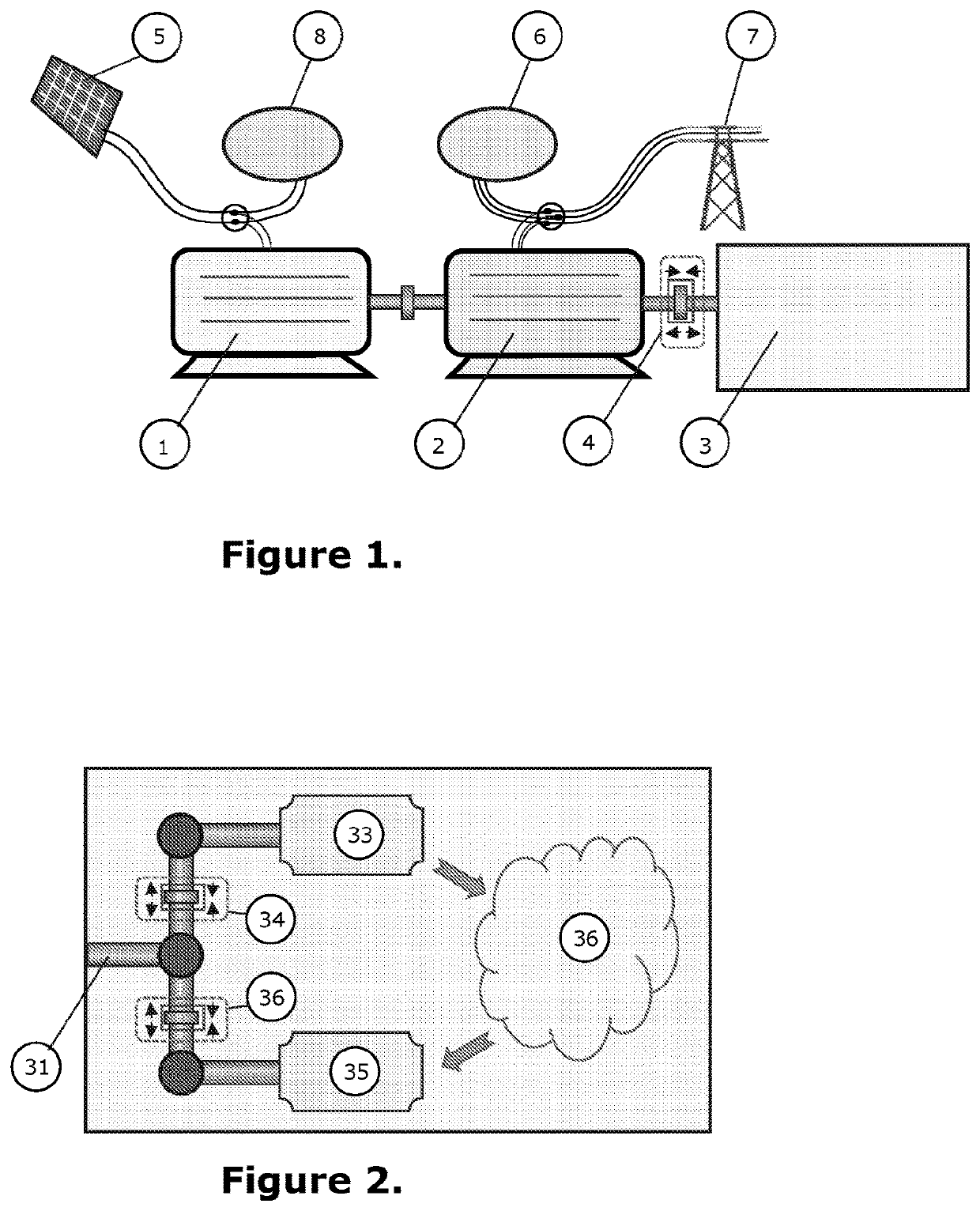
[0040]FIG. 1 shows a schematic diagram of the simplest representation of this system. This figure shows a DC electrical machine (1), such as a rotating DC motor / generator, comprising a DC rotor (along with other typical DC electrical machine components such as a stator and the like) directly-coupled to an AC electrical machine (2). The AC electrical machine 2 is also typically a rotating AC motor / generator and comprises an AC rotor (and other AC electrical machine components such as a stator and the like). The DC rotor and the AC rotor are mechanically coupled and form a composite electrical machine.

COMPONENTS OF THIS INVENTION

[0041]The essential components of the system of this invention are:[0042](1) A DC electrical machine[0043](2) An AC electrical machine coupled directly to the above DC machine[0044](3) A (thermo-)mechanical energy storage system (TMESS)[0045](4) A clutch capable of coupling / de-coupling the pair of electrical machines from the central shaft of the (thermo-)mech...


PUM


Abstract

A system for power conversion and energy storage is described. In an embodiment the system comprise a DC rotating electrical machine (1) comprising a DC rotor; an AC rotating electrical machine (2) comprising an AC rotor; and a (thermo-) mechanical energy storage system (known as a TMESS) (3). The TMESS comprises a central shaft, said central shaft charged and discharged with shaft power and selectively mechanically coupled to the DC rotor and to the AC rotor via clutch (4) to form a shaft train. Some source of DC generation such as photovoltaic cells (5) feeds electrical power into the DC electrical machine (1). There may also be local DC loads (8) supported by the system. The AC electrical machine (2) may deliver power to local AC loads (6), or draw power from the AC electrical grid (7).

Description

FIELD OF INVENTION[0001]The current invention relates to a system for power conversion and energy storage, in particular to a system comprising a DC rotating machine, an AC rotating machine and an energy storage device.BACKGROUND OF THE INVENTION[0002]Power generation from renewable energy sources (especially the sun and wind) is already (in 2019) less expensive than other generation forms based on so-called Levelised Cost of Electricity (LCoE), which simply divides the total electrical energy output by the corresponding marginal cost. As the penetration of renewable energy increases, it becomes important to consider how to reconcile the supply of electricity with the demand for it. Energy storage is one of the primary options for this balancing—and it can be a complete solution.[0003]Some renewable energy generation naturally generates DC (direct-current) electricity. Photovoltaic (PV) panels are the most common instance of renewable energy generators that produce DC and because of...

Claims


Application Information

Patent Timeline
IPC IPC(8): H02J3/28H02J15/00H02P5/60
CPCH02J3/28H02P5/60H02J15/006H02J3/30H02J15/00H02J15/007H02J2300/24H02J2300/28Y02E10/56Y02E60/16Y02E70/30
Inventor SIMPSON, MICHAEL
Owner CHEESECAKE ENERGY LTD
Learn More