
A flame detection and ignition device

a technology of ignition device and flame detection, which is applied in the manufacture of sparking plugs, combustion types, lighting and heating apparatus, etc., can solve the problems of complex and expensive devices of known optical scanners in common use, and achieve the effect of simple and efficient assembly of ionisation and/or ignition devices

Pending Publication Date: 2022-05-19
JOHN ZINK CO LLC
View PDF0 Cites 0 Cited by
  • Summary
  • Abstract
  • Description
  • Claims
  • Application Information

AI Technical Summary

Benefits of technology

The patent describes a device and method for easily attaching an ionization and ignition device to a surface. The device has an inner rod that can be made into a suitable shape for high temperature applications, while the outer sleeve, which is easier to manipulate, can be attached to a surface using a variety of means. The device is easy to manufacture and performs reliably. The method is simple and efficient for assembling the device. The device allows for safe and effective ignition and ionization in a compact design.

Problems solved by technology

However, known optical scanners in common usage are complex and expensive devices.

Method used


Image

  • A flame detection and ignition device
  • A flame detection and ignition device
  • A flame detection and ignition device

Examples


Embodiment Construction

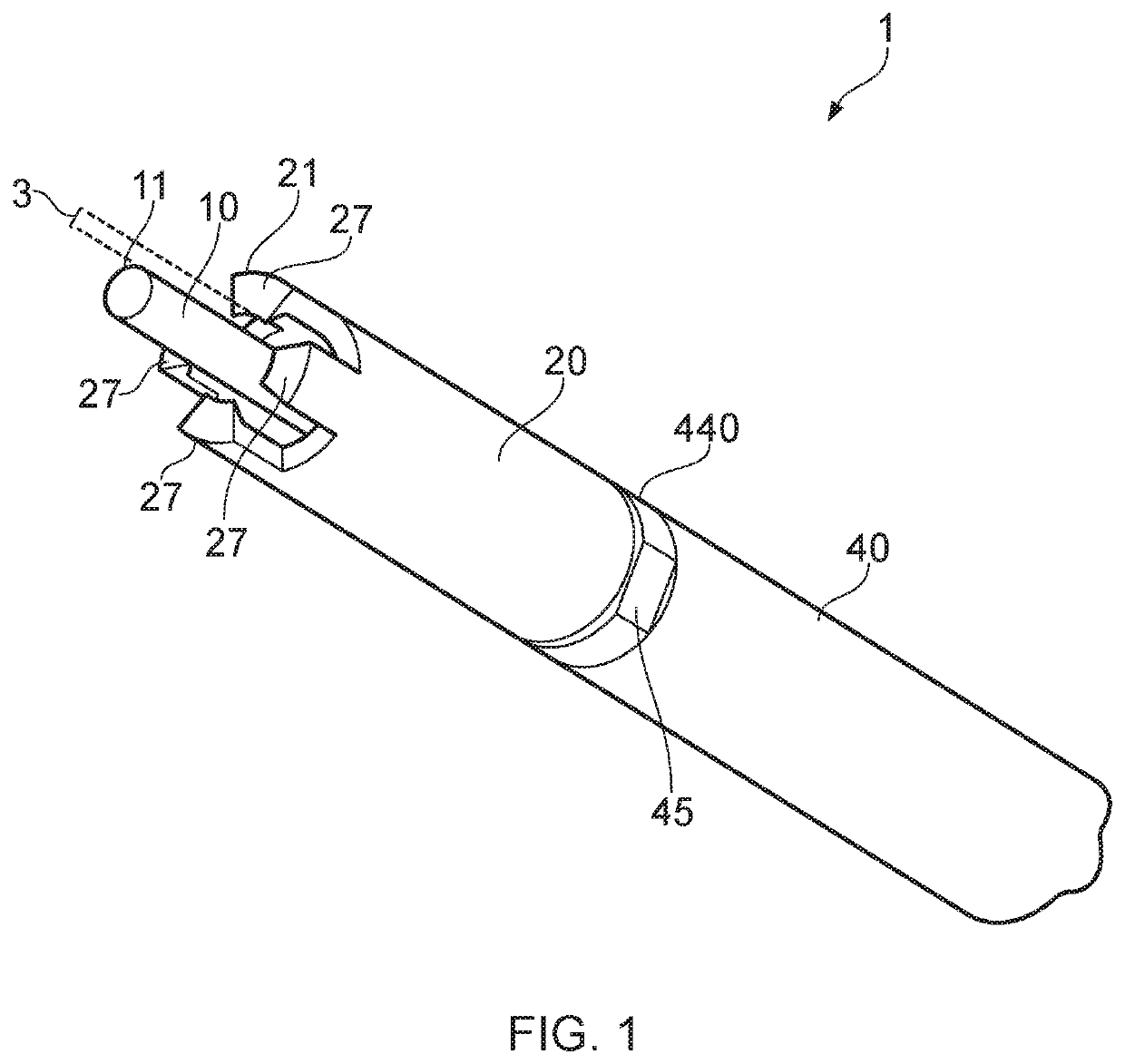
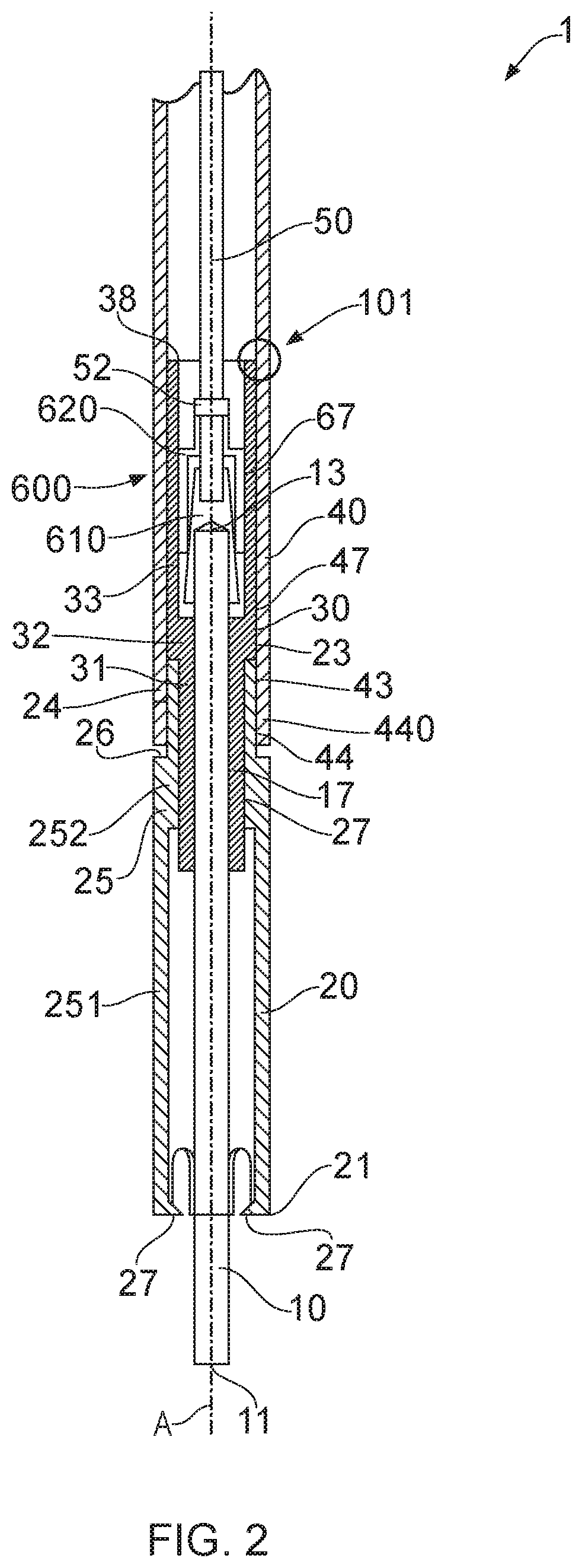
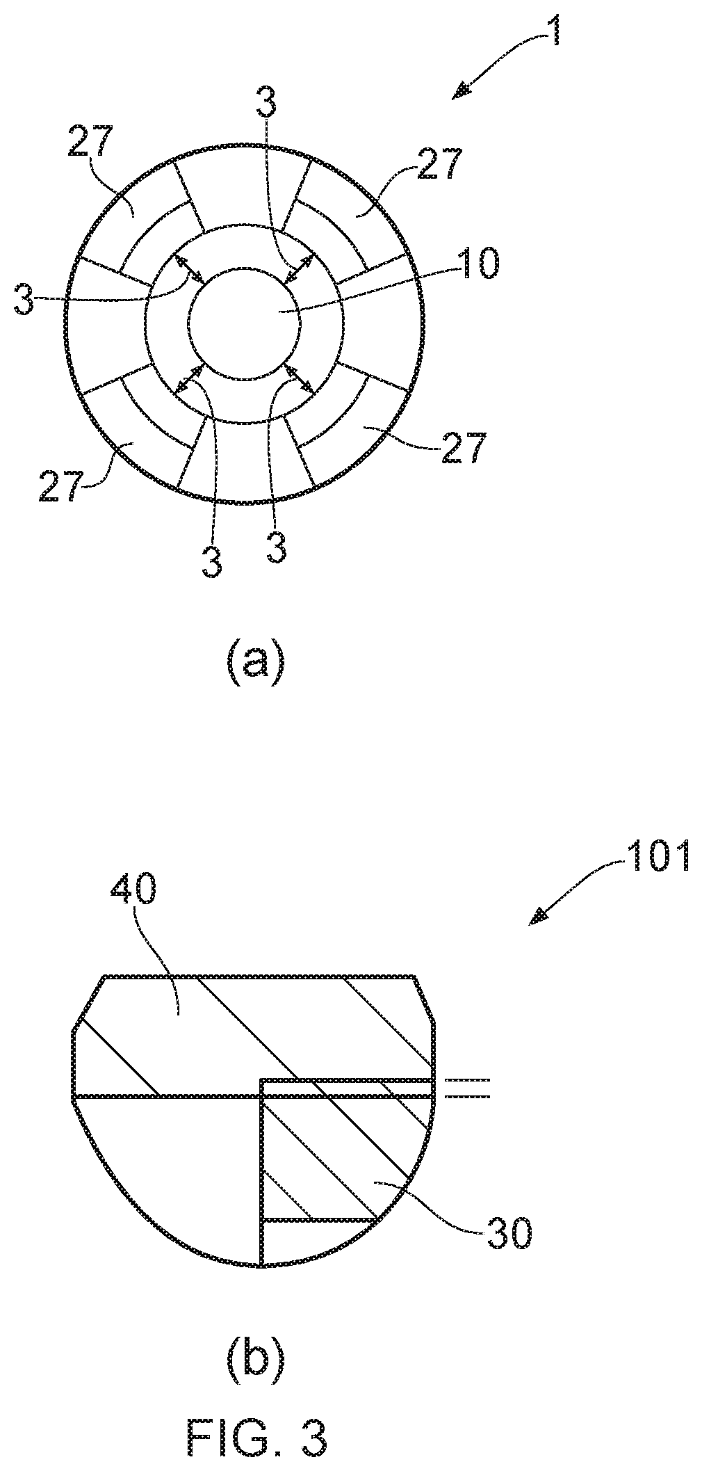
[0038]FIG. 1 shows an embodiment of a flame ionisation detection and / or ignition device 1 incorporating features of the present invention.

[0039]As described above, devices according to embodiments of the invention can be used for one or both of two purposes. In some applications, the device is used as a flame ionisation detection device. In other applications, the device can be used as a flame ignition device. In still further applications, the device can be used as both a flame detection and ignition device. As will become evident from a reading of the following specification, certain properties can be adapted to enable the device to perform in an improved manner in either one, or both, of those functions. A skilled reader will be aware of how electrical control systems can be applied to the device described herein to utilise the illustrated devices as either flame ionisation detection and / or ignition devices and so such control systems are not described in detail. The novel featur...


PUM

PropertyMeasurementUnit
temperaturesaaaaaaaaaa
Young's Modulusaaaaaaaaaa

Abstract

There is disclosed an ionisation and / or ignition device comprising: an inner rod, an outer sleeve, and an electrical insulator. The inner rod comprises a semiconductor refractory material. The outer sleeve comprises a semiconductor refractory material. The electrical insulator is disposed between the inner rod and the outer sleeve. The inner rod material has a greater hardness than the outer sleeve material.

Description

TECHNICAL FIELD[0001]The present invention relates to a device configured to be used for either or both of flame detection and / or flame ignition in an industrial burner. In particular, the invention relates to a flame detection and / or ignition device having an improved construction, which combines manufacturability with an ability to withstand high temperature applications.BACKGROUND[0002]It is known to use an electrode as a detector for ionisation that can occur at high temperatures, for example a high temperature within a flame or site of combustion.[0003]UK patent number 879,482, filed on 13 Aug. 1959, describes a flame detector which has an electrode comprising a refractory semiconductor material, for monitoring the presence of a flame in a furnace. The electrode comprises an active portion consisting of a rod of silicon carbide, which can be arranged in a hole in the furnace wall and project into the furnace. The detector further comprises an electric circuit configured such th...

Claims


Application Information

Patent Timeline
Patent Type & Authority Applications(United States)
IPC IPC(8): F23D14/72F23Q3/00H01T21/02H01T13/20
CPCF23D14/725H01T13/20H01T21/02F23Q3/004F23N5/12H01T13/39H01T13/32H01T13/467F23N5/126
Inventor GRILLOTTI, DOMINIQUETHEIS, GILLESBRESILLION, CLEMENT
Owner JOHN ZINK CO LLC
Learn More